
Last Updated on June 21, 2025
Recently, I needed a basic and cost effective variable power supply with Voltage and Current range display for prototyping and small electronics component testing on my bench. So that i have designed one, I have used the LM7805 and LM317 in many of my earlier projects, but this time I wanted to integrate both a fixed 5V output and an adjustable 1.25V to 24V output in the same setup. For VI range display i have used DSN-VC288 module, which is a digital Volt Ammeter for DC Power supply. Finally this circuit helped me out, and so that I’m sharing it here for anyone building DIY bench power supplies. Let’s break down the circuit step by step and understand how it works, and how you can build one for yourself using commonly available components.
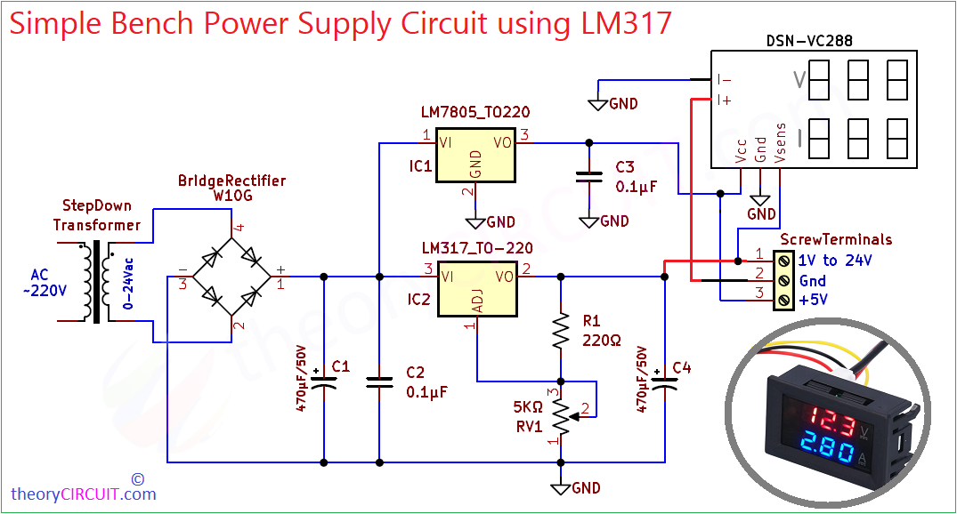
The following bench power supply circuit designed with Step down transformer to reduce the main power supply 220V ~ 240V AC to 24V AC (Remember High Voltage AC power supply is dangerous handle with extreme care), then Bridge Rectifier for AC to DC Conversion and then Voltage Regulators finally Digital Display module to show output Voltage (V) and output Current I in (Amps).
Circuit Diagram
Components Required
| 1 | C1, C4 | 470μF/50V | CP_Radial_D5.0mm_P2.50mm | 2 | ||
| 2 | C2, C3 | 0.1μF | C_Disc_D3.8mm_W2.6mm_P2.50mm | 2 | ||
| 3 | R1 | 220Ω | R_Axial_DIN0207_L6.3mm_D2.5mm_P10.16mm_Horizontal | 1 | ||
| 4 | ScrewTerminals1, to-DSN-VC288 | Screw_Terminal_01x03 | TerminalBlock_bornier-3_P5.08mm | 2 | ||
| 5 | BridgeRectifier1 | W10G | Diode_Bridge_Round_D9.8mm | 1 | ||
| 6 | IC1 | LM7805_TO220 | TO-220-3_Vertical | 1 | ||
| 7 | IC2 | LM317_TO-220 | TO-220-3_Vertical | 1 | ||
| 8 | RV1 | 5KΩ | Potentiometer_Alps_RK09K_Single_Horizontal | 1 | ||
| 9 | J1 | 24V AC Input | TerminalBlock_bornier-2_P5.08mm | 1 | ||
| 10 | J2 | to DSN-VC288 Isens | TerminalBlock_bornier-2_P5.08mm | 1 |
Construction & Working
This circuit constructed in three stages,
- Step Down Transformer
- Voltage Regulators
- Digital Display Module
Operation of this circuit starts with a 220V ~ 240V AC input to the step down transformer, which is step down to 24V AC and this is taken from the secondary winding terminals. This AC supply is fed to a bridge rectifier module W10G, and then converted to DC supply, due to its pulsating nature we have to filter it by using filtering capacitors. Here C1 470µF/50V makes smooth DC supply by filtering high peak voltages in rectified DC. A ceramic disc capacitor C2 0.1µF is also used here to suppress high frequency noise which is highly recommended for power supply design.
Voltage Regulator LM317 and LM7805
The filtered DC supply is now applied to two voltage regulator ICs, here LM7805 fixed +5V regulator is used for powering Digital Volt Ammeter module DSN-VC288. When we measure High dc voltage this module requires separte fixed operating voltage that is why we use LM7805.
Main voltage regulator in this circuit is LM317, which provides an adjustable output voltage ranging from 1.25V to 24V (output tolerence depends on input voltage and heatsinking). Here the output voltage is set by using R1 220Ω and RV1 5KΩ Potentiometer. Output voltage can be calculated as,
Output Voltage = 1.25 × (1 + RV1/R1)
You can adjust and fine tune RV1 to vary the output voltage. Capacitor C4 (470µF) filters the output again for smooth voltage delivery.
To monitor the output voltage and current flow to the load, this circuit includes a DSN-VC288 dual digital display module. Make the wiring as given in the diagram, then only you can measure both V and I.
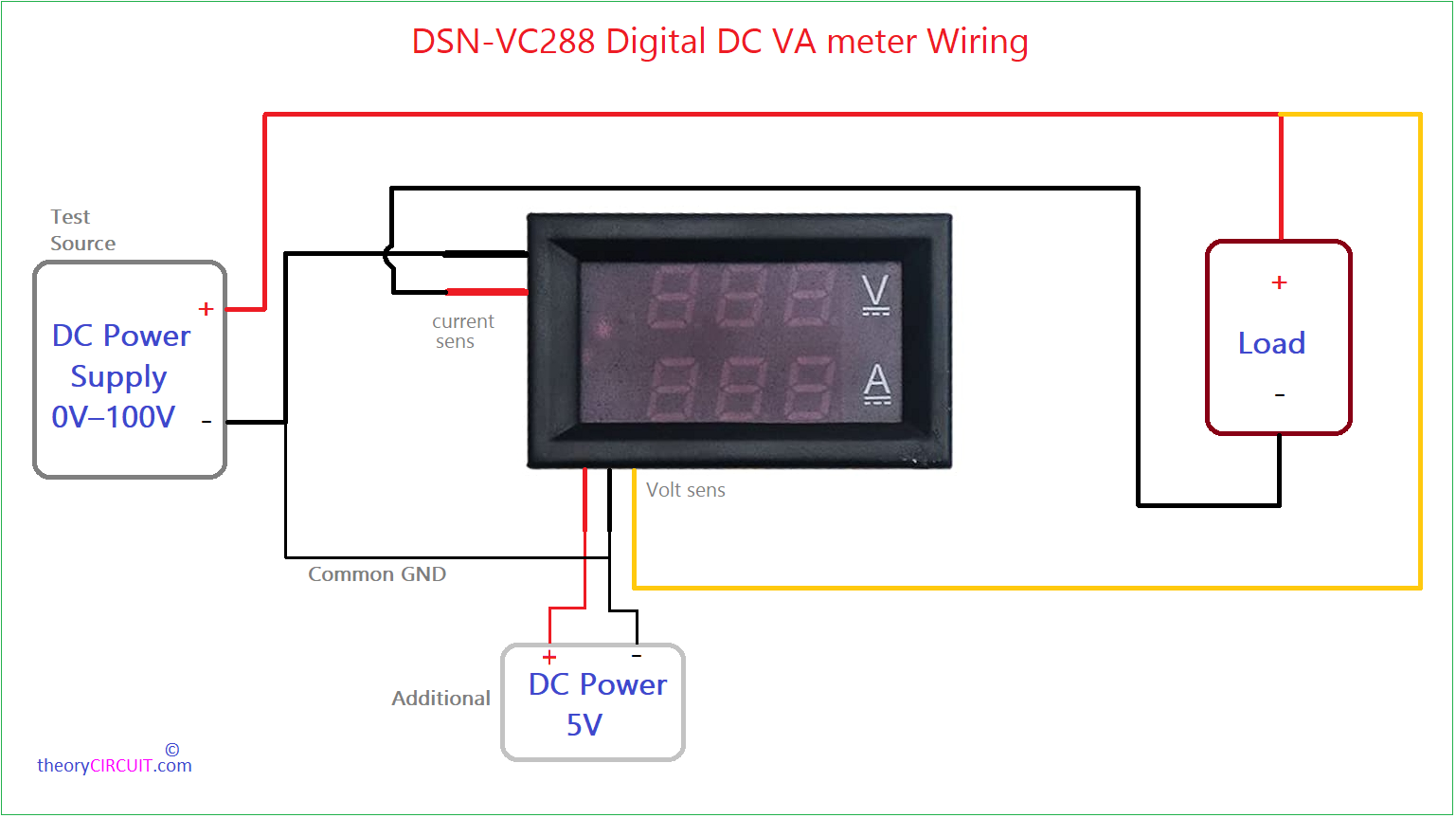
Output from the LM7805 used as Additional (separate) power supply to display module, I- and GND terminals are connected to common Ground in the power supply circuit. Volt sense terminal is connected to the LM317 output (+V to load) then load – or GND terminal is connected to the I+ (current sense) terminal of display module.
Simple Cardboard prototype
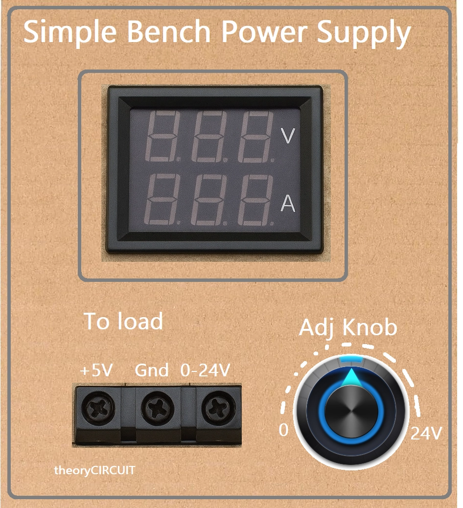
Note: Here the +5V DC is fixed and will not show in Digital Display module.
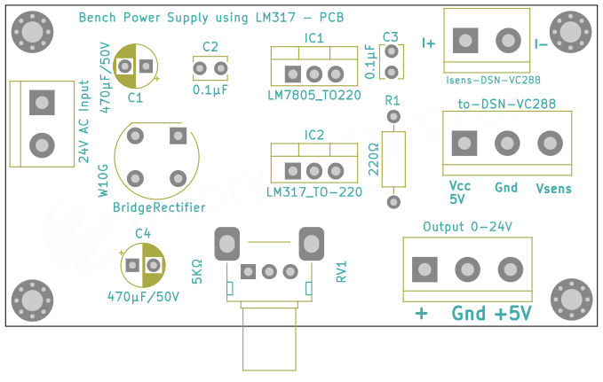
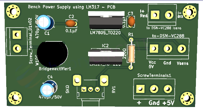
Printed Circuit Board
Simple Bench Power Supply using LM317 PCB Gerber Files.
Component Placement on Bench power supply lm317 PCB
Interactive Board Viewer


3D View of PCB
Testing
Here i used Relay coil as a load and adjusted different output voltage and current. It works fine. You can use Resettable Polyfuse (RE135 – which can hold 1.35 Amps, gets trip in 2.7 Amps and handle 60V) in positive output line for extra safety. Use heatsink for LM317 for long duration high current output handling. This circuit delivers maximum 1.5A output current.