
Last Updated on March 24, 2024
Reading DC Fan RPM (Revolutions per minute or Rotation per minute) is very easy than we think, yes because DC fan internally contains Hall Effect sensor, So we need to count the output pulse from the Hall Effect sensor that’s it.
Lets start with Pinout of DC fan, 3 wire and 4 wire DC fan available in the market you can choose any one of them.
3 Wire DC FAN
In this tutorial I have used three wire 12V DC fan (D60SH-12) from yateloon Electronics.

This Fan internally contains a small Hall-Effect sensor to aware how fast the fan blades are rotating. Here we can use this sensor output and Interface with Arduino to serially print RPM value. It has Red wire for +Vcc, and black for Ground supply finally the Yellow gives signal output. Pull up resistor gives strength to the signal and may connected to external micro-controller.
4 Wire DC FAN
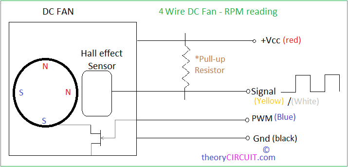
As like 3 wire DC fan this is also contains hall effect sensor and has 4 wires, Red for +Vcc, black for Gnd, Yellow/White for signal output from Hall sensor and Blue for PWM signal viz we can control speed of fan by varying PWM signal.
Component Requirements
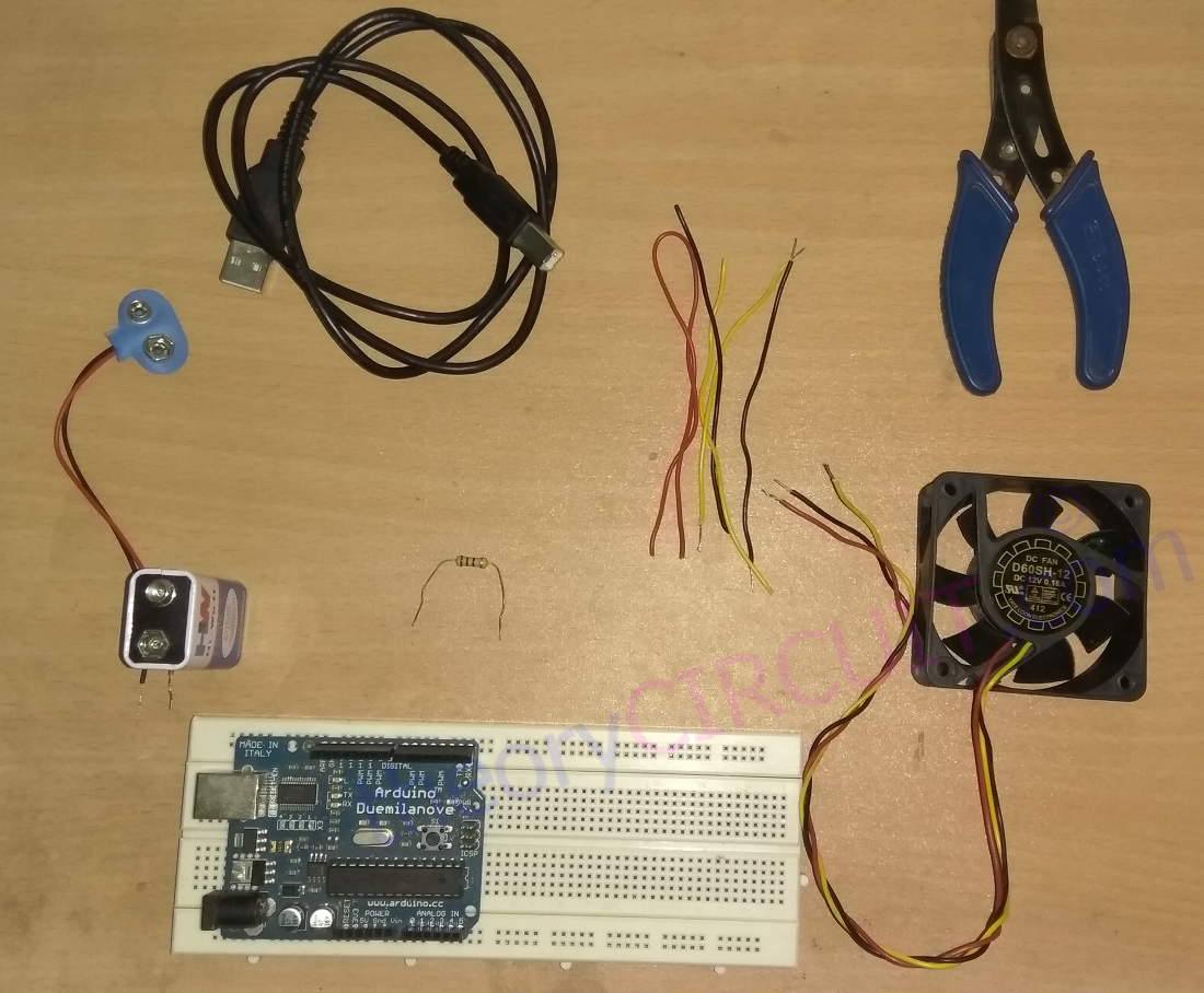
To make it possible you need Arduino Board (UNO, Genuino, mega, etc..,any one you have), Subject DC fan make sure it contains internal hall effect sensor, 9V Battery with clip to give separate bias to Fan, a 560Ω Resistor, and Connecting wires.
Arduino DC fan Hookup
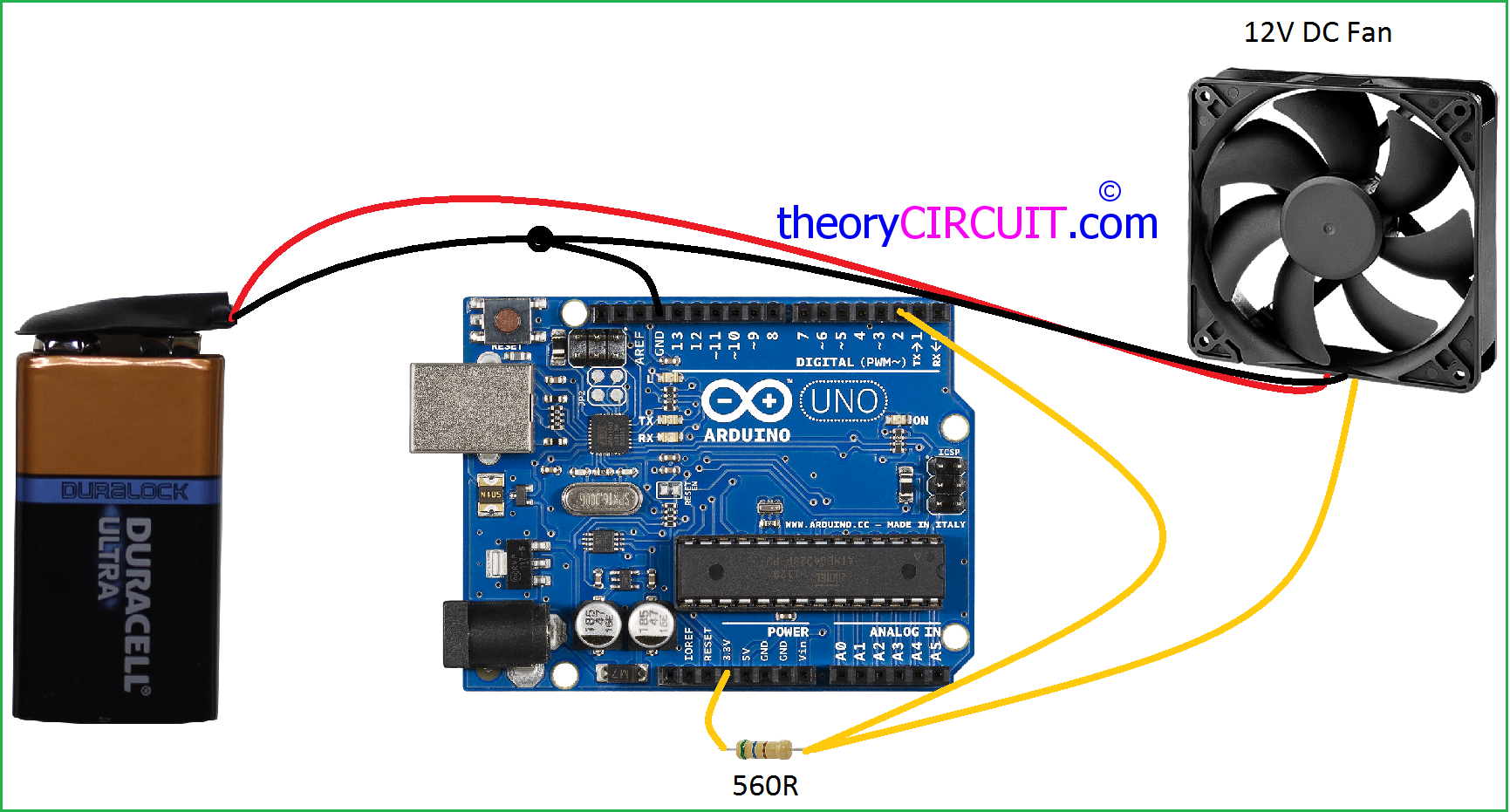
Connect 560Ω Resistor in 3.3 V bias of Arduino board and connect Resistors another end to Fan signal pin (yellow wire) & Arduino Digital pin D2 together. Connect battery to DC Fan and bring common ground to Arduino board as shown in image. Connect the battery clip to the battery after uploading following sketch.
Schematic Diagram
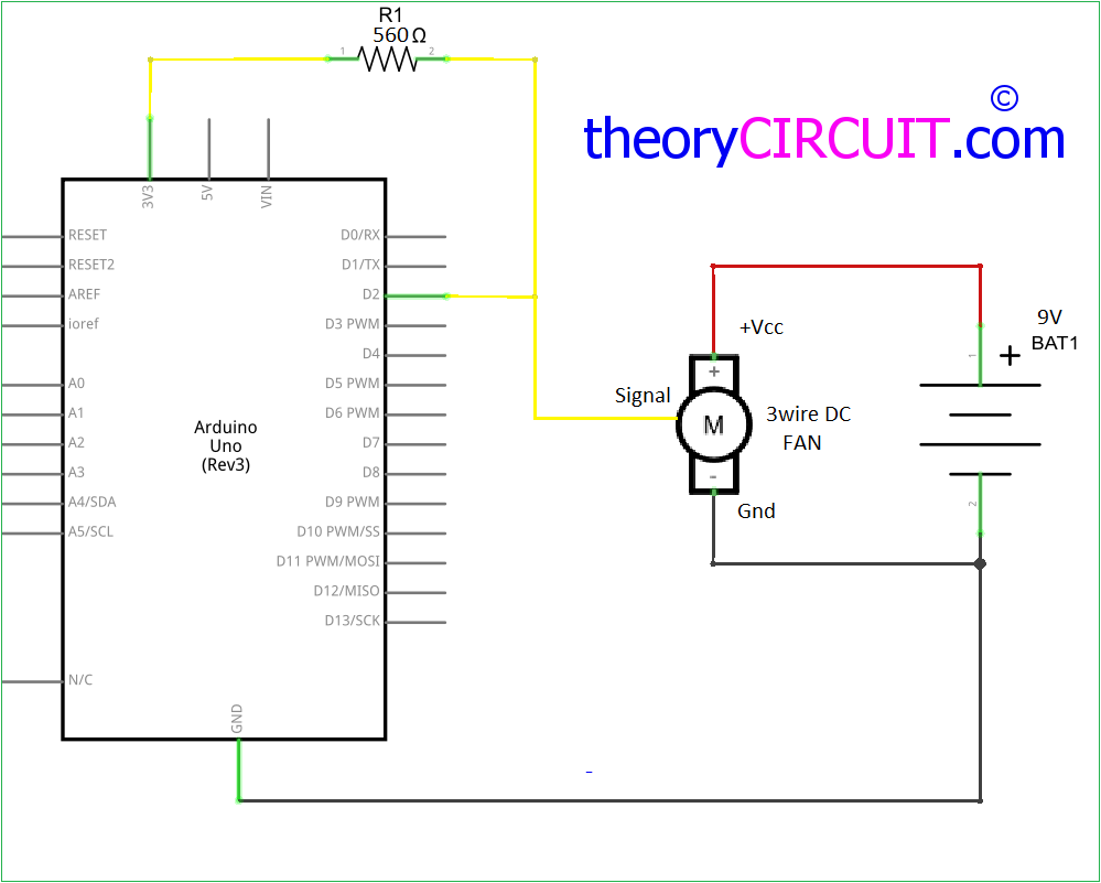
Just given for details, Schematic represents same connections as in the Arduino DC fan Hookup image.
Arduino Sketch
//project done by www.theorycircuit.com
//code by Crenn from http://thebestcasescenario.com  thank you!
//Varibles used for calculations
int NbTopsFan; int Calc;

//The pin location of the sensor
int hallsensor = 2; typedef struct{

//Defines the structure for multiple fans and
//their dividers
char fantype;
unsigned int fandiv; }fanspec;

//Definitions of the fans
//This is the varible used to select the fan and it's divider,
//set 1 for unipole hall effect sensor
//and 2 for bipole hall effect sensor
fanspec fanspace[3]={{0,1},{1,2},{2,8}}; char fan = 1;

void rpm ()
//This is the function that the interupt calls
{ NbTopsFan++; }

//This is the setup function where the serial port is initialised,
//and the interrupt is attached
void setup()
{ pinMode(hallsensor, INPUT);
Serial.begin(9600);
attachInterrupt(0, rpm, RISING); }

void loop ()
//Set NbTops to 0 ready for calculations
{ NbTopsFan = 0;

//Enables interrupts
sei();

//Wait 1 second
delay (1000);

//Disable interrupts
cli();

//Times NbTopsFan (which is apprioxiamately the fequency the fan
//is spinning at) by 60 seconds before dividing by the fan's divider
Calc = ((NbTopsFan * 60)/fanspace[fan].fandiv);

//Prints the number calculated above
Serial.print (Calc, DEC);

//Prints " rpm" and a new line
Serial.print (" rpm\r\n");
}
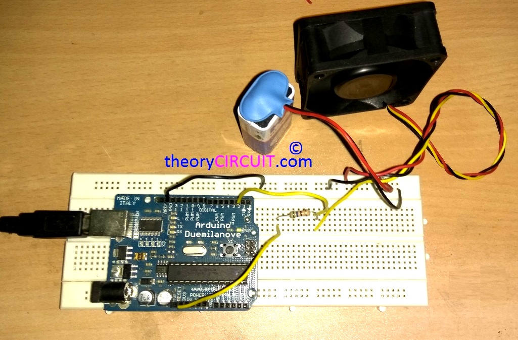
Prototype
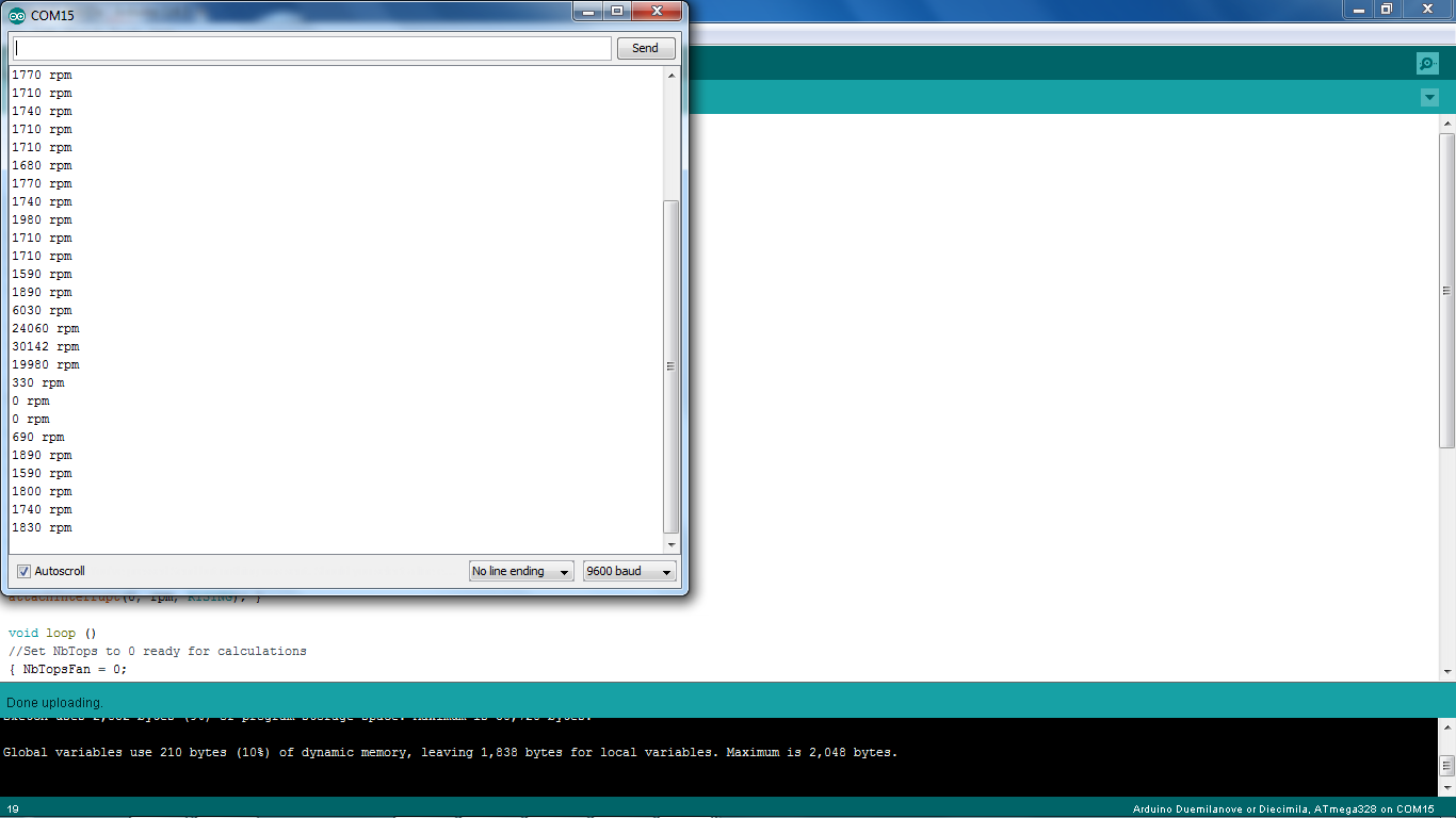
Serial Monitor
are you sure the yellow line is for control? most fans i’ve seen put a pulse per revolution signal so you can measure the fan RPM.
what is and how to define {{0,1},{1,2},{2,8}} in the fanspec fanspace[3]={{0,1},{1,2},{2,8}}?
how to choose from kind of fan ?
ray, did you ever figure out ….
“what is and how to define {{0,1},{1,2},{2,8}} in the fanspec fanspace[3]={{0,1},{1,2},{2,8}}?
how to choose from kind of fan ?”
This works for me, but parts of it are over my head, and yet I think it’s what I need.
Be CAREFUL!
This depends on how you connect your fan. In the circuit given it is fine. However if you were to switch your fan OFF with an NPN from the Arduino by switching the ground return of the fan the RPM sense lead on the fan, in my case, reads 11Volt when it’s idle.
This will probably fry the arduino input pin or the 3.3v pin.
always connect the pullup to the Arduino Vcc (5 or 3v3). Seems to me it will be hard toget 12V on the RPM line……yet, safe to always check
It works perfectly 🙂
two questions,
1- Can I use 12V with the same resistor?
2- How can I measure Multiple fans? in my case 16.
Thanks a lot:)
Can it read RPM at 70 % duty cycle? For me it does not work I get weird values ???
Can the resistor’s value be different than 560R?
Can it read RPM with pwm fan?