
Last Updated on March 16, 2024
A basic Arduino project to control RGB LED color output by using Variable Resistors, here varying the Resistors value changes the duty cycle of PWM signal produced by Arduino and the output colors of RGB LED.
RGB LED
There are two types of RGB LED 1. Common Anode LED, 2. Common Cathode LED both are functionally same and both RGB LED has three internal LED filaments and glows corresponding light when gets supply (Colors from LED, to get details about How LED makes colors? ).
The Red, Green and Blue are called as primary colors and by mixing each other with different intensity we may get 16 Million color outcomes.

In this Project we are going to use Common Anode RGB LED almost all follows the same pin configurations, if you have any doubt about pins use 2.0V to 2.5V supply and self check each pins to get exact pinout of you RGB LED.
LED Pinout
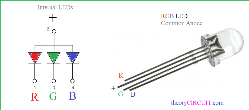
This LED contains four pins the first one is cathode terminal of Red internal LED and 2 pin is Common Anode for all internal LEDs and 3 pin is cathode of Green finally 4 pin is cathode pin of Blue.
Arduino RGB LED Hookup

Connect the pin Common Anode pin of RGB LED to +5V pin of Arduino board and connect Red, Green and Blue terminals to Arduino digital pins D9, D10 and D11 followed by 220Ω Resistor. Connect three variable Resistors first pin to +5V and third pin to GND of Arduino board. Connect Second pins of Variable resistors to A0, A1 and A2 separately here A0 for Red, A1 for Green and A2 for Blue color Values.
Schematics
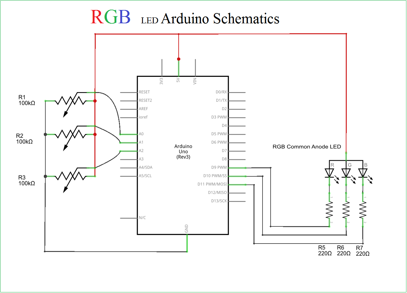
Connect all components and upload the following Arduino code.
RGB LED Arduino Code
// Name the Pins used for PWM output to RGB LED
const int redPin = 9;
const int greenPin = 10;
const int bluePin = 11;

// Name the Pins used for 100K pots (You can use different value)
const int redPotPin = 0;
const int greenPotPin = 1;
const int bluePotPin = 2;

// Init our Vars
int currentColorValueRed;
int currentColorValueGreen;
int currentColorValueBlue;

void setup()
{
  pinMode(redPin, OUTPUT);
  pinMode(greenPin, OUTPUT);
  pinMode(bluePin, OUTPUT);
}

void loop()
{
// Read the voltage on each analog pin then scale down to 0-255 and inverting the value for common anode
  currentColorValueRed = (255 - map( analogRead(redPotPin), 0, 1024, 0, 255 ) );
  currentColorValueBlue = (255 - map( analogRead(bluePotPin), 0, 1024, 0, 255 ) );
  currentColorValueGreen = (255 - map( analogRead(greenPotPin), 0, 1024, 0, 255 ) );

// Write the color to each pin using PWM and the value gathered above
  analogWrite(redPin, currentColorValueRed);
  analogWrite(bluePin, currentColorValueBlue);
  analogWrite(greenPin, currentColorValueGreen);

}
After uploading sketch to arduino board, now vary the Resistor values to see the different color output from RGB LED.
I don’t understand this 100k pots, what is this.
this is VR all right.