Last Updated on March 16, 2024
Important thing for plant growth and life is water for proper plant hydration we need to pour water regularly and when soil get dry. Here is the simple soil dryness detector circuit to help you to identify the dryness of water in your plant soil or where ever needed.
We have designed this simple Soil dryness detector circuit by employing two NPN transistors as switch and a buzzer element to produce beep sound when there is no water on soil. In this circuit we use insulation removed copper wires as sensor here or you can use any conducting material or nail as a moisture detecting sensor.
Circuit Diagram
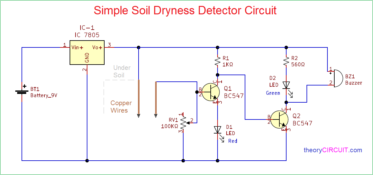
A Simple Soil Dryness Detector Circuit or soil moisture sensing circuit, designed by using Transistor, LED and Buzzer, addresses crucial aspects of plant care and Water resource management. This circuit proves invaluable in optimizing watering schedules by providing real-time feedback on soil moisture, preventing overwatering or underwatering of plants. Here some updated version with single transistor and solar power implementation.
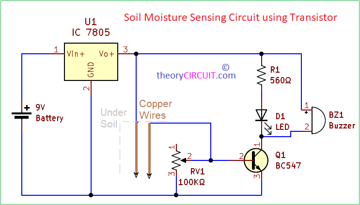
Single Transistor Soil moisture sensing circuit
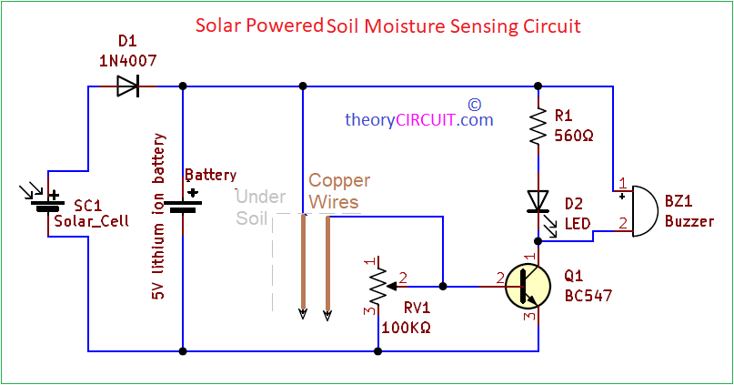
Solar Powered soil moisture sensing circuit
Components Require
- Battery 9V
- Regulator IC 7805
- Conducting Copper wire (or) nail
- Variable Resistor 100KΩ
- Resistors 1KΩ, 560Ω
- Transistor BC547 (NPN) = 2
- LED Red, Green each one
- Buzzer
- 5V solar cell
- Diode 1N4007
Construction & Working
Start with the Soil moisture detector to construct this circuit, Here we have used two insulation removed copper wires as a detector you can use two nails also and you need to put those detectors in the soil up to your detection range. Don’t put copper wire or nails too near it may come to contact each other.
9V battery supply is regulated by the Regulator IC 7805 and applied to the two transistor switches and to the soil moisture detector setup (sensor). Another terminal from sensor is applied to the Q1 transistor base here you can vary the sensitivity level by using RV1. When there is moisture in the soil then Q1 becomes turn ON due to the positive supply flow through sensor to base, if the soil being dry then Q1 stays in turn OFF position and all bias through Q1 collector flows to Q2 Base terminal and Q2 gets turn ON and makes buzzer to produce beep sound. Here Green LED indicates enough moisture on the soil and Red LED indicates dryness on the soil.
Operation of all circuits are same but the single transistor circuit gives only one indication and solar cell can be used to replace 9V battery source.
Bad. Not work.
Can you describe?