Last Updated on March 16, 2024
Not Enough Bass Sound on your subwoofer then try this simple DIY circuit to improve your woofer speaker performance. This circuit is constructed by using TDA2030 IC, and this is intended for use as a Low frequency class-AB amplifier. It provides 14 watts output, by adding another stage it may give output upto 30 watts.
For better performance this circuit needs split power supply with one amps current rating and use heat sink over TDA2030 IC to avoid thermal run away.
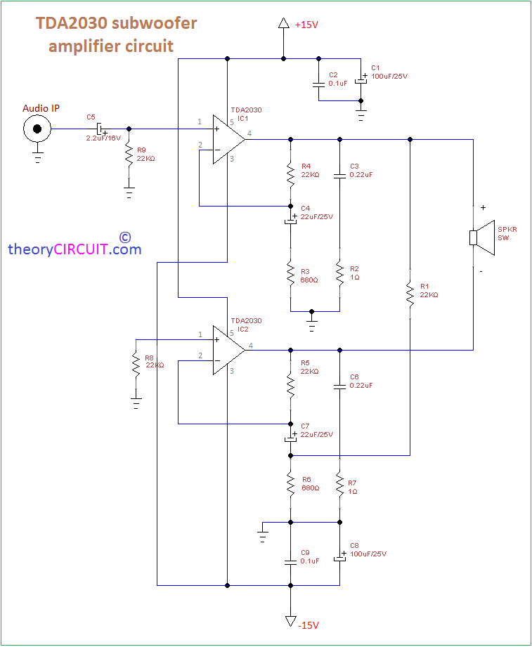
Circuit Diagram
Construction & Working
Before going to the circuit operation details let we see the main part of this circuit,
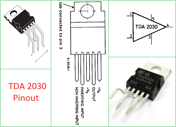
This IC comes in Pentawatt Horizontal package, and has the wide range of operating voltage upto 36V, and it is capable of working in single or split power supply.
The subwoofer amplifier circuit constructed by using two TDA2030 amplifiers, upper side amplifier output is connected to the speaker +ve terminal and lower side amplifier O/P is connected to the -ve terminal of speaker. Audio input applied to the non inverting input of IC1 and IC2 non inverting input grounded through R8 resistor, each amplifier taking feedback through inverting input. This circuit uses Split power supply (+15V, GND, -15V). By using this Bridge amplifier configuration we can get output power upto 30 watts.
Well elaborated function of tda ic 2030 be blessed
resistors require how many watts
2 Watts each.
Left channel Background noise. How it reduce?
Is there any frequency filter in this circuit? If yes, how to remove it so I can get a normal full range mono sound?
Sub woofer sound is very low duel speaker ok what is problem?
Is there any frequency filter in this circuit? If yes, how to remove it so I can get a normal full range mono sound?
There isnt any filter in the circuit posted above.if u want to use it for subwoofer it either u use an active lowpass filter or pass type
good sound, but after some time the ic will be overheat and burnt out, even if use a large heat sink and coolig fan, power supply given 12-0-12, 4A
can you obtain 60watt power output using the tda2030 and with a low pass filter?
I want to see the internal structure of tda2030
See datasheet….
So, you have pretty much plagiarised the circuit form the datasheet ? Nice one, not.
BTW… one would be better off using a TDA2065( or alike) in a “bridge'” configuration, as show in its datasheet.
Much simpler, and better performance.