
Last Updated on April 15, 2024
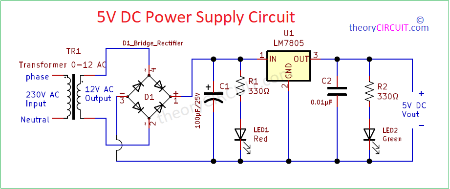
5V Power Supply Circuit is the common and most required circuit for electronic devices and digital logic gates. Here is the 5V DC supply schematic to provide reliable and stable DC voltage output. To design 5V power supply, we need to study the basic requirements like available input power source, Power supply Stepdown method and output current range, then filtering method (Inductive load requires proper filtering and reverse protection). If you are designing 5V adapter then you have to place indicator LED to show the presence of supply out. Given 5V power supply schematic is designed for common requirement and applications, It uses linear positive voltage regulator IC 7805, It is suitable for all kind of 5V / 1A bias based projects.
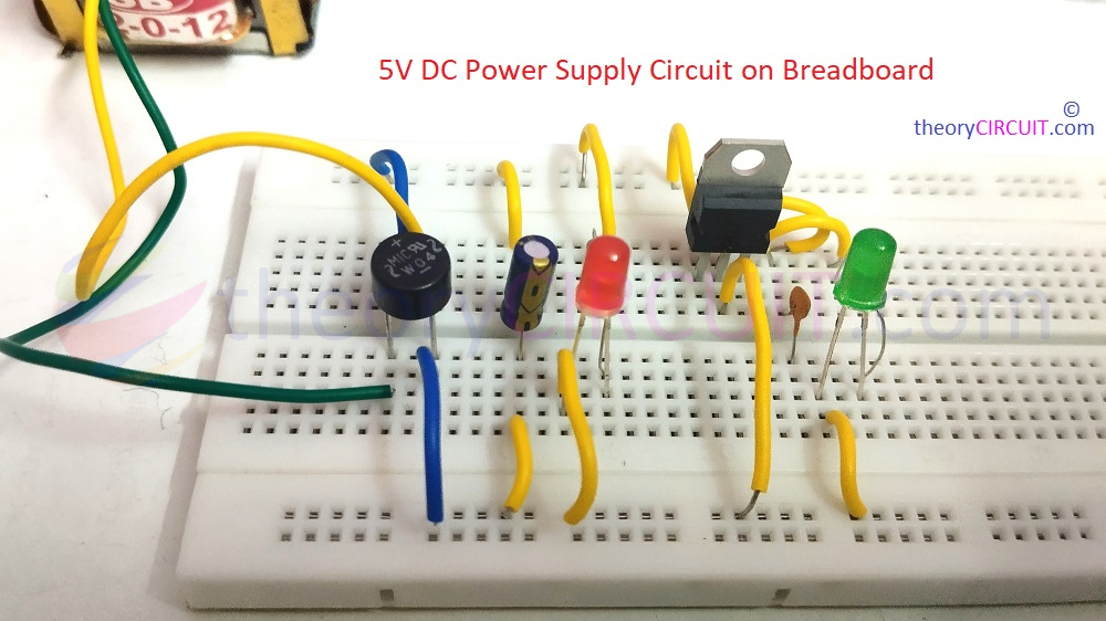
Most Electronic Circuits and Devices or Microcontrollers Requires 5V DC power supply circuit. We use Integrated Circuit LM7805 (Positive Voltage Regulator) to give Regulated Constant 5 Volt DC from unregulated DC supply. In this Article a simple easy to construct 5V DC power supply circuit designed and tested.
To indicate the presence of Input Voltage and Output Voltage here we used two LEDs. This Circuit designed to work as a Independent power source for electronic devices and circuits.
Circuit Diagram
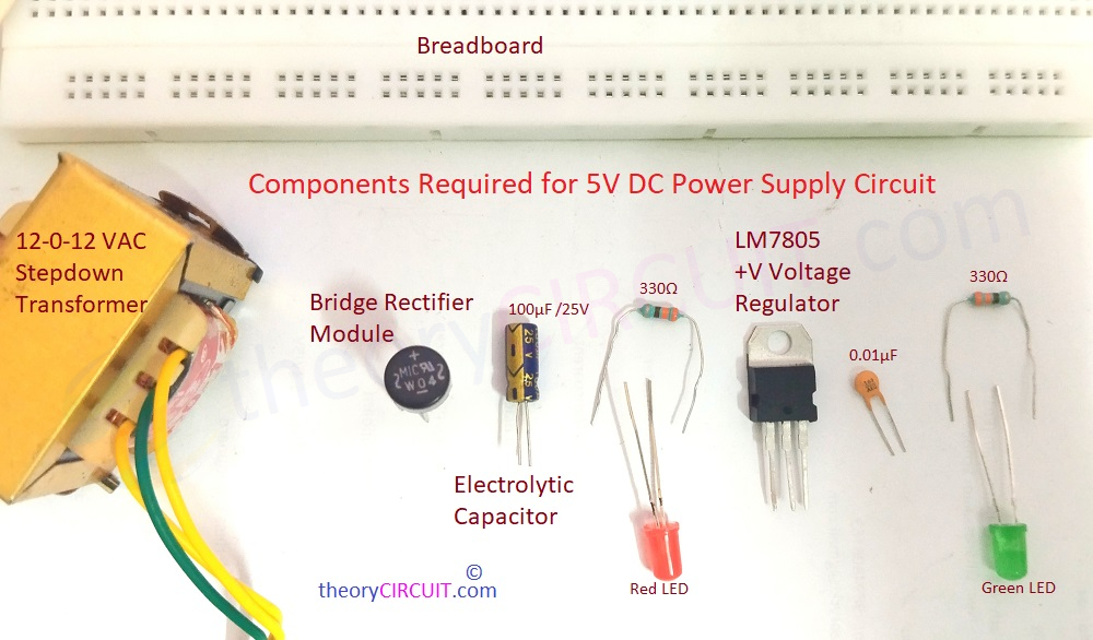
Components Required (BOM)
| S.No | Designator | Value | Part Number | Quantity |
| 1 | TR1 | 230V to 0-12V AC | 0-12V Stepdown Transformer | 1 |
| 2 | R1, R2 | 330Ω | – | 2 |
| 3 | C1 C2 | 100µF/25V 0.01µF | Electrolytic Disc capacitor | 1 1 |
| 4 | D1 | – | Bridge Rectifier Module | 1 |
| 5 | U1 | LM7805 | LM7805_TO220 | 1 |
| 6 | LED1 LED2 | Red Green | – – | 1 1 |
Video
Construction & Working
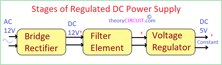
Every DC power supply circuit (Not SMPS) may have these stages to give Regulated Constant DC power supply. Here 230V AC main supply step down to 12V AC by using Step down Transformer then Bridge Rectifier module Converts AC supply to DC supply after that to Remove unwanted AC ripples from DC supply filter elements (Capacitor C1) used. After filter element we get 12 Volt DC supply, to Reduce this supply IC LM7805 employed here, at the output terminal of LM7805 we get constant Regulated 5V DC supply.
IC LM7805
This LM78XX series of fixed-voltage integrated-circuit voltage regulators is designed for a wide range of Regulator applications. These applications include on PCB board regulation for elimination of noise and distribution problems associated with single point regulation. Each of these regulators can deliver up to 1.5 A of output current. The internal
current-limiting and thermal shutdown features of these regulators essentially make them immune to overload.
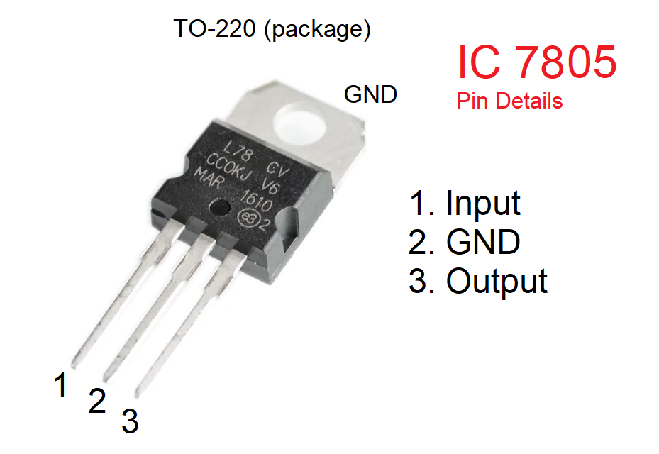
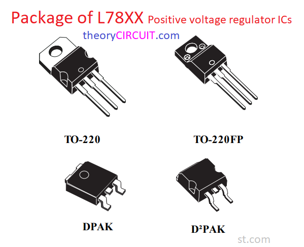
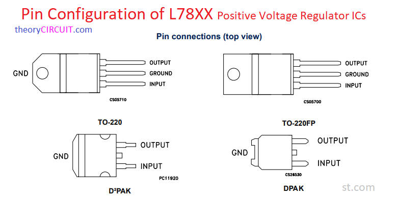
Some notable features of LM7805 Positive voltage regulator are,
- 3-Terminal Regulators
- Output Current up to 1.5 A
- Internal Thermal-Overload Protection
- High Power-Dissipation Capability
- Internal Short-Circuit Current Limiting
- Output Transistor Safe Area Compensation, For more information refer datasheet.
Note: –
- Choose step down transformer from 500mA to 1.5A, because the maximum current rating of IC LM7805 is 1.5A.
- Choose All Resistors in 1 Watts range.
Lets say the output voltage from the single phase 230V to 0-12 V transformer (used) is 12 V, how come that the input voltage to the filter is 12 V since there is a voltage drop of about 1.4 V (due to the rectifier) ?
Wouldn’t the capacitor that stabilizes the DC voltage after the rectifier correct that problem !?!?!?
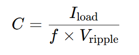
How to calculate C1 ?
C1 in this schematic is picked from the available components, but works well (practically), you can calculate it by using the formula
i replace Bridge Rectifier Module is 4007 diode?