
Last Updated on March 7, 2025
ESP32 Microcontroller from Espressif systems have many features like Wi-Fi, Multifunctional GPIOs, Internal Sensors and Bluetooth. ESP32 supports Classic Bluetooth (BR) and Bluetooth Low Energy (BLE), which allows wireless communication with devices like smart phones, tablets, computers and also BLE enabled sensors. Here we are going to explore how to control an LED connected to an ESP32 using Bluetooth Classic method and Serial Bluetooth terminal App on a Smartphone.
ESP32 Microcontrollers are familiar for wireless and IoT projects, one of its underrated feature is Bluetooth, by using it we can make home automation, sensor reading and more., Let’s learn it through controlling an LED via BT.
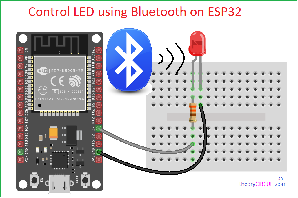
Wiring Diagram
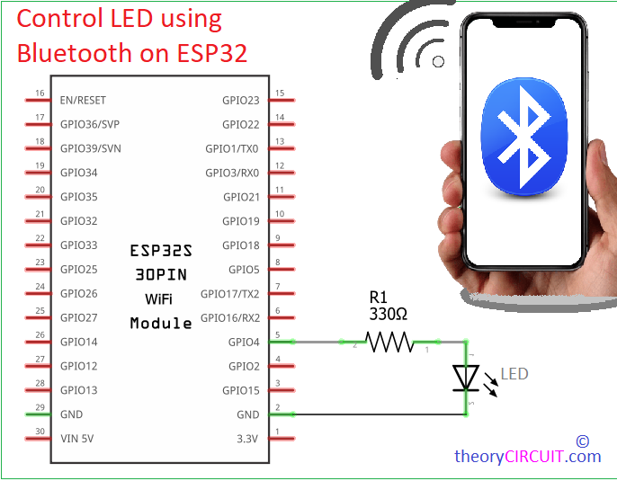
Circuit
Components Required
- ESP32 Development Board (e.g., ESP32-WROOM-32, ESP32 Devkit V1)
- LED (any color, typically 3mm or 5mm)
- Resistor (R1 – 330Ω for current limiting)
- Breadboard and Jumper Wires
- Computer with Arduino IDE and USB Cable (for programming and power)
- Smartphone with the Serial Bluetooth Terminal app installed (available on Google Play Store)
Working Video
Construction & Working
Here is our goal is to control an LED connected to GPIO4 (You can change as your wish – remember to change it in code also) of the ESP32 by sending ‘1’ to turn it ON and ‘0’ to turn it OFF and showing message when there is wrong data send.
Just connect a Resistor R1 to GPIO4 pin and then Anode terminal of an LED then GND to Cathode terminal of LED, After completing hardware wiring, Install Serial Bluetooth Terminal App in your smartphone. From this App we are going to send control data to the ESP32 chip via Bluetooth.
Code
/* Code from theoryCIRCUIT.com */
#include <BluetoothSerial.h>

// Check if Bluetooth is available
#if !defined(CONFIG_BT_ENABLED) || !defined(CONFIG_BLUEDROID_ENABLED)
#error Bluetooth is not enabled! Please run `make menuconfig` to enable it
#endif

// Create BluetoothSerial object
BluetoothSerial SerialBT;

// Define LED pin
const int ledPin = 4;  // GPIO4

void setup() {
  // Initialize LED pin as output
  pinMode(ledPin, OUTPUT);
  digitalWrite(ledPin, LOW);  // LED off initially

  // Initialize Serial for debugging
  Serial.begin(115200);

  // Initialize Bluetooth with device name
  SerialBT.begin("ESP32-BT-tc");  // Bluetooth device name
  Serial.println("Bluetooth Started! Pair with ESP32-BT-tc");
}

void loop() {
  // Check if data is available from Bluetooth
  if (SerialBT.available()) {
    char incomingChar = SerialBT.read();

    // Ignore newline (\n) and carriage return (\r)
    if (incomingChar == '\n' || incomingChar == '\r') {
      return;  // Skip processing these characters
    }

    // Process received commands
    switch (incomingChar) {
      case '1':  // Turn LED ON
        digitalWrite(ledPin, HIGH);
        SerialBT.println("LED is ON");
        Serial.println("LED is ON");
        break;

      case '0':  // Turn LED OFF
        digitalWrite(ledPin, LOW);
        SerialBT.println("LED is OFF");
        Serial.println("LED is OFF");
        break;

      default:  // Unknown command
        SerialBT.println("Send '1' to turn LED ON, '0' to turn LED OFF");
        Serial.println("Unknown command received: " + String(incomingChar));
        break;
    }
  }
  delay(20);  // Small delay to prevent overwhelming the processor
}
In this code each line Instruction given with description. ESP32 device Bluetooth is named as ESP32-BT-tc. Upload this code to ESP32 and see the serial monitor of Arduino IDE to display “Bluetooth Started! Pair with ESP32-BT-tc” If it is not showing just press “EN” button on ESP32.
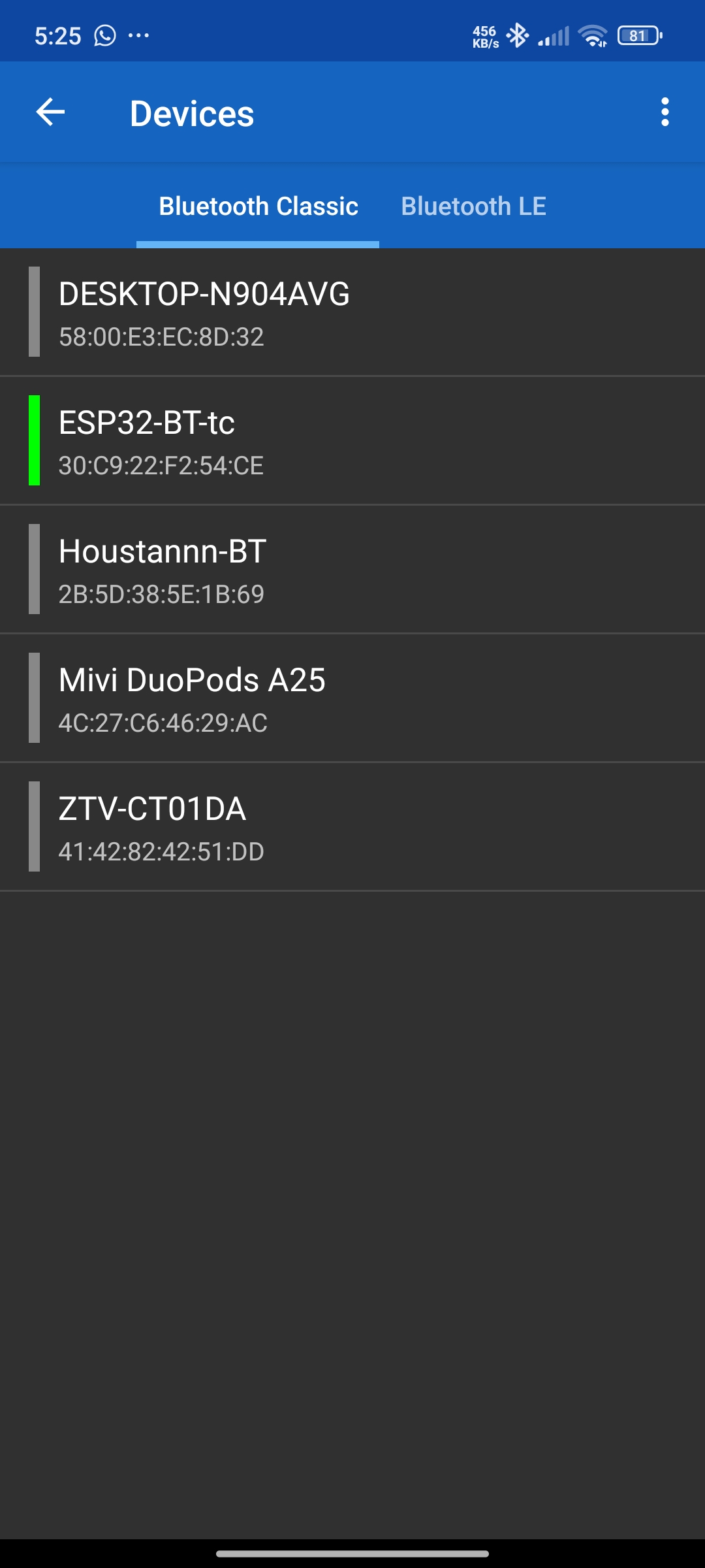
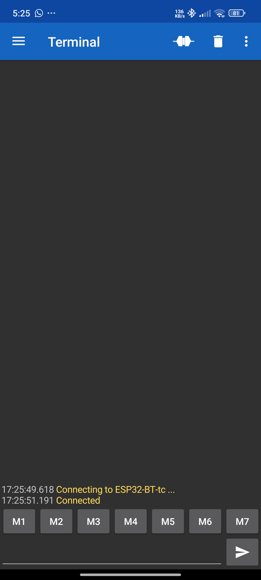
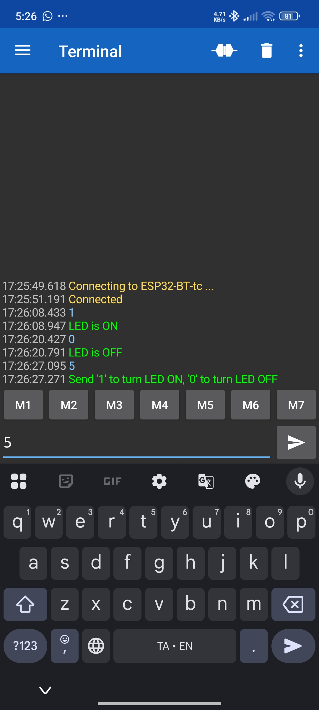
Now in the “Serial Bluetooth Terminal” App select menu bar and choose Bluetooth Classic and you see the ESP32-BT-tc name then select it and it will automatically pair your smartphone and ESP32 board. Now you are ready to send command ‘1’ for LED ON, ‘0’ for LED OFF others will show the info message.