
Last Updated on October 4, 2025
We use bulky Audio Amplifiers to drive speaker, In case you need to drive single speaker and medium sound output is ok then you can try the following simple audio amplifier circuits and avoid bulky amplifiers. Here we have listed to 5 World’s simplest Audio amplifier circuit, these are uses single amplifying components instead of complex high power IC. As we know we can build Class A Amplifier using BJT and MOSFET, we just tried to test it by applying bias an audio signal.
- Single Transistor Audio Amplifier
- BC547 Audio Amp (Inverted)
- 2N2222A Audio Amplifier
- C1815 Audio Amplifier
- IRF540N MOSFET Audio Amplifier
All these amplifiers are configured in Class A and using 8Ω loud speaker as load, you can power these circuits from 5V to 9V. Let’s look at each circuit and its operation.
1. Single Transistor Audio Amplifier Circuit
Components used
- Transistor BC547 NPN
- Loud speaker 8Ω
- Resistor 2KΩ (2.2KΩ)
- Capacitor 10μF
Construction & Working
This Amplifier circuit uses a BC547 NPN Transistor as a main Amplifying element. Input Audio signal is connected to the transistor base terminal through 10μF Electrolytic Capacitor (C1), here this capacitor blocks DC and allows only AC audio signal to the transistor. If you getting filtered Audio signal then no need for C1 (coupling capacitor), you can directly connect it to the base terminal. Speaker (8Ω) is connected between +Vcc and collector terminal, here it is act as RL. Collector to base supply flows through R1 (2KΩ) Resistor and emitter of bc547 connected to GND.
When the audio signal enters through the capacitor or directly to base, it changes the transistor’s base current, due to the transistor’s current gain (hFE), this small input drives a large current through the collector, emitter path which drives loud speaker.
This Class A amplifier configuration makes transistor to conduct entire input signal cycle and gives continuous amplification.
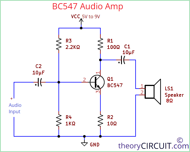
2. BC547 Audio Amp Circuit
Components used
- Transistor BC547 NPN
- Loud speaker 8Ω
- Resistor 100Ω
- Resistor 10Ω
- Resistor 2.2KΩ
- Resistor 1KΩ
- Capacitor 10μF = 2
Construction & Working
This BC547 Audio Amplifier can be used after Pre Amplifier. Direct Audio Input can drive speaker but in Inverted form. This is also in a Class A Configuration. For base terminal, voltage divider placed to give power supply and maintains proper DC level around 1.6V to 1.8V so that transistor stays in Active mode for audio signal amplification. R1 Resistor (100Ω) is connected at the collector to limit the current through the transistor and protect it from over loading. R2 (10Ω) Resistor is connected to emitter to prevent distortion due to thermal effect. C1, C2 used as a coupling capacitors. This circuit can give 0.5W output.
3. 2N2222A Audio Amplifier Circuit
Components used
- Transistor 2N2222A NPN
- Loud speaker 8Ω
- Resistor 100Ω
- Resistor 10Ω
- Resistor 2.2KΩ
- Resistor 1KΩ
- Capacitor 10μF
Construction & Working
In previous Circuit we just changed Transistor by replacing BC547 with 2N2222A, which will have higher output current and gives much louder output sound through speaker. Biasing components are same as previous circuit. Input coupling capacitor C2 only removed. If you are having voltage difference between audio source and amplifier circuit then you can use one coupling capacitor.
4. C1815 Audio Amplifier Circuit
Components used
- Transistor C1815 NPN
- Loud speaker 8Ω
- Resistor 100Ω
- Resistor 10Ω
- Resistor 2.2KΩ
- Resistor 1KΩ
- Capacitor 10μF
Construction & Working
During the experiments with small signal amplifiers, one transistor gives considerably low noise output, That one transistor is C1815, It is a low noise, general purpose NPN Transistor that is widely used in Audio frequency (AF) applications.
We just placed this transistor in the previous circuit with proper terminal alignments and observed low noise output sound from loud speaker. Here you can use input coupling capacitor when required otherwise, you don’t need to place.
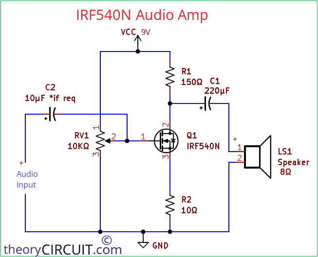
5. IRF540N Audio Amplifier Circuit
Components used
- MOSFET IRF540N N-Channel
- Loud speaker 8Ω
- Resistor 150Ω
- Resistor 10Ω
- Variable Resistor 10KΩ
- Capacitor 10μF
Construction & Working
Just moved to Voltage Controlled Device from Current Controlled Device. Instead of BJT, here we used MOSFET. It has Higher Frequency and current handling ability so that we just tried to amplify the Audio signal with IRF540N. We have connected Variable Resistor as a voltage divider and connected its junction with Gate terminal, Audio input signal also connected with Gate terminal. Here MOSFET in a common source configuration.
Speaker is connected with Drain terminal, when the Gate supply manipulated by the Audio signal then it changes the supply in Drain terminal and makes loud speaker to produce sound.
Working Video
Look at Interactive Board Viewer
BC547 Audio Amp Circuit PCB Gerber File.


Note:-
- If you encounter over heat in Resistor (mostly R1 here) then just change its watts range (from 1/4W to 1, 2W)
- Use heat sink for MOSFET
- If you are using Laptop, Mobile, or PC for Audio source or other low power output (headphone jack), then you don’t need input coupling capacitor.
- Use DC power supply less than 1 Amps current rating, here in the circuit we don’t have drop out setup.