
Last Updated on March 16, 2024
Electrically Erasable Programmable Read Only Memory (EEPROM) is a type of non volatile memory that retains its stored data even when the power is turned off. EEPROM allows for data storage that persists through power cycles. We can Erase, Store and Read Data multiple times with the specific device Address lines. When the Microcontroller needs additional storage we can use this type of memory, for an example the Arduino UNO has only 32K bytes of Flash memory and 2K bytes of SRAM, If we are in the position to log sensor data we can use additional memory like EEPROM. In this Article you can learn how to Interface Two Wire Serial EEPROM with Arduino.
IC AT24C02 Two wire Serial EEPROM from ATMEL which is now a part of Microchip Technology. This specific EEPROM device, part of the AT24Cxx series, is known for its compact size and versatility, making it an excellent choice for various embedded systems and electronic applications. AT24C02 is 2KB memory internally organized with 32 pages of 8 bytes each, the 2K requires an 8-bit data word address for random word addressing. It utilizes the I2C (Inter-Integrated Circuit) or Two Wire Serial protocol for communication, which is well-supported by the Arduino platform. This makes it an ideal choice for interfacing with Arduino boards, including the Arduino Uno.
AT24C02 Pinout
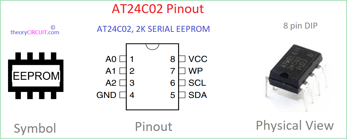
| Pin No. | Pin Name | Pin Function |
| 1 | A0 | Address Input |
| 2 | A1 | Address Input |
| 3 | A2 | Address Input |
| 4 | GND | Ground supply |
| 5 | SDA | Serial Data Line |
| 6 | SCL | Serial Clock Line |
| 7 | WP | Write Protect |
| 8 | VCC | Positive Power Supply |
- The A2, A1 and A0 pins are device address inputs that are hard wired for the AT24C02. As many as eight devices may be addressed on a single bus system.
- The SCL input is used to positive edge clock data into each EEPROM device and negative edge clock data out of each device.
- The SDA pin is bidirectional for serial data transfer.
- WP – Write Protect pin that provides hardware data protection. The Write Protect pin allows normal Read/Write operations when connected to ground (GND). When the Write Protect pin is connected to VCC, the write protection feature is enabled.
AT24CXX Series EEPROM comes in 1KB to 16KB Memory size with different packages. Refer Datasheet for more information.
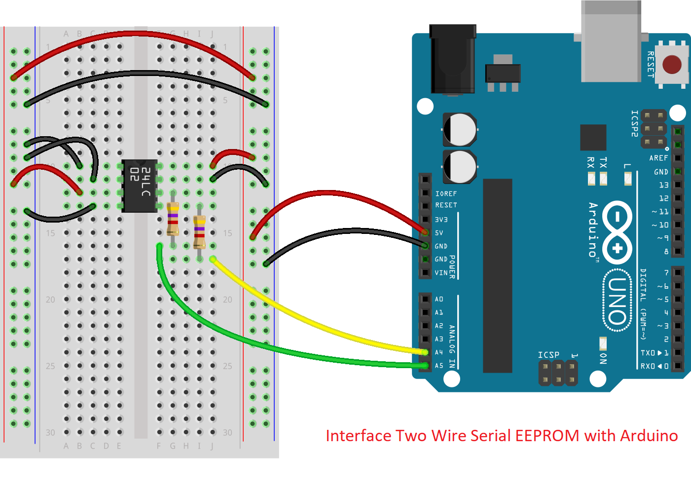
Circuit Diagram
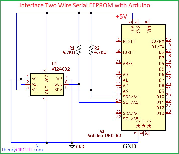
Interfacing EEPROM with Arduino
Construction & Working
| IC AT24C02 EEPROM | Arduino Uno |
| Pin 1 A0 | GND |
| Pin 2 A1 | GND |
| Pin 3 A2 | +5V |
| Pin 4 GND | GND |
| Pin 5 SDA | A4 |
| Pin 6 SCL | A5 |
| Pin 7 WP | GND |
| Pin 8 VCC | +5V |
AT24C02 can be connected with any microcontroller or processor having I2C communication feature. It requires only Device Address, power supply and SDA-SCL interface. Provide Pull up Resistors if you are not sure about microcontroller internal pull up Resistor. Connect Arduino board with EEPROM IC as mentioned in the tabulation. Here we have selected (100) as device address by connecting A2 in HIGH (+5V) and A1, A0 in LOW (GND). This device Address should appear in Arduino Code. Check the power supply of Arduino and EEPROM module and then EEPROM’s SDA and SCL lines to the Arduino’s I2C lines.
Operation of AT24C02 EEPROM depends on four conditions.
1.CLOCK and DATA TRANSITIONS
2.START CONDITION
3.STOP CONDITION
4.ACKNOWLEDGE
5.STANDBY MODE
6.MEMORY RESET
The SDA pin is normally pulled high with an external Resistor. Data on the SDA pin may change only during SCL low time periods. Data changes during SCL high periods will indicate a start or stop condition
START CONDITION: A high-to-low transition of SDA with SCL high is a start condition which must precede any other command.
STOP CONDITION: A low-to-high transition of SDA with SCL high is a stop condition. After a read sequence, the stop command will place the EEPROM in a standby power mode.
ACKNOWLEDGE: All addresses and data words are serially transmitted to and from the EEPROM in 8-bit words. The EEPROM sends a zero to acknowledge that it has received each word. This happens during the ninth clock cycle.
STANDBY MODE: Low power standby mode which is enabled: (a) upon power-up and (b) after the receipt of the STOP bit and the completion of any internal operations.
MEMORY RESET: After an interruption in protocol, power loss or system reset, any 2-wire part can be reset by following these steps.
* Clock up to 9 cycles.
* Look for SDA high in each cycle while SCL is high.
* Create a start condition.
Arduino Code
/* Example Arduino Code for Read Write Operation in EEPROM
 *  AT24C02
 */
#include <Wire.h>

#define ADDR_Ax 0b100 //A2, A1, A0 Address Lines
#define ADDR (0b1010 << 3) + ADDR_Ax

void setup() {

  Serial.begin(9600);
  Wire.begin();
  writeI2CByte(0, 1);
  Serial.println(readI2CByte(0));
}

void loop() {
  // Void Loop

}

void writeI2CByte(byte data_addr, byte data){
  Wire.beginTransmission(ADDR);
  Wire.write(data_addr);
  Wire.write(data);
  Wire.endTransmission();
}

byte readI2CByte(byte data_addr){
  byte data = NULL;
  Wire.beginTransmission(ADDR);
  Wire.write(data_addr);
  Wire.endTransmission();
  Wire.requestFrom(ADDR, 1);
  delay(1);
  if(Wire.available()){
    data = Wire.read();
  }
  return data;
}