
Last Updated on March 24, 2024
To automate processes or set up alerts within a specific time frame, a Timer circuit becomes indispensable. The 1 Minute Timer Circuit presented here is particularly efficient, utilizing the well-known Timer IC 555 and a few readily available components. Operating as a Monostable Multivibrator, this circuit consistently produces a low output but switches to a high output for a specified period (in this case, calibrated to 1 minute) upon receiving a Trigger signal. The output is connected to an LED and two-pin screw terminals, allowing for the connection of a buzzer or other actuators. The Timing Resistor is represented by Variable Resistor RV1, which can be tuned as needed. For those preferring a fixed resistor, the value can be calculated using the Monostable Multivibrator Calculator.
IC 555 Pinout
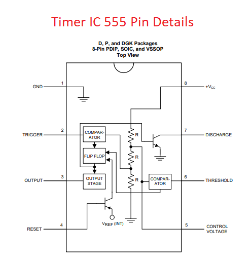
| Pin Number, Name | Description |
| 1, GND | Ground supply |
| 2, TRIGGER | External trigger pulse applied to this pin |
| 3, OUTPUT | Output Pin |
| 4, RESET | -Ve pulse applied to this pin to disable or reset the time |
| 5, CONTROL VOLTAGE | Controls the threshold and trigger levels |
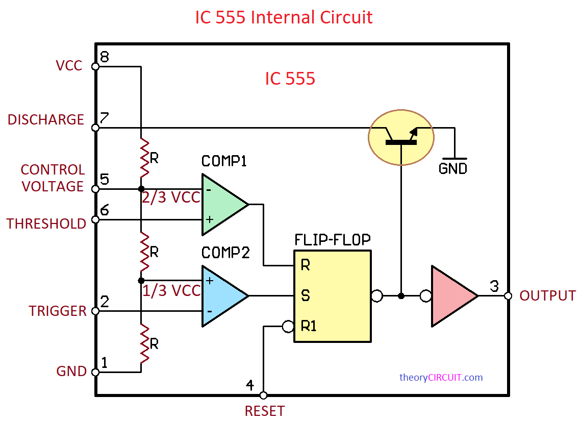
| 6, THRESHOLD | Compares the voltage applied to the terminal with a reference voltage of 2/3 Vcc. |
| 7, DISCHARGE | Open collector output which discharges a capacitor between intervals. toggles the output When 2/3 Vcc. |
| 8, +VCC | Positive supply for IC |
This Timer operates in three modes,
- Astable Multivibrator
- Monostable Multivibrator
- Bistable Mode
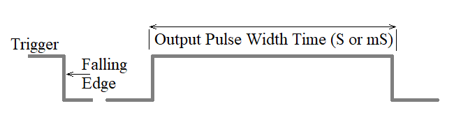
In all modes IC 555 Oscillates pulse depends on the timing elements. For Astable mode continuously Oscillates square pulse at chosen duty cycle. For Monostable only one pulse when ever the trigger input applied. For Bistable timer ic oscillates two stable state output when the trigger input applied.
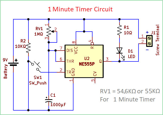
Circuit Diagram
Components List
- Timer IC NE555P
- Pushbutton Switch
- Variable Resistor 1MΩ
- Resistor 10KΩ, 10Ω
- Capacitor 1000μF/16V
- LED
- Screw Terminal 2 pin
- Battery 9V
Construction & Working
To construct the One Minute Timer Circuit, the trigger pin should be connected to the ground supply through the push button switch. When the push button switch pressed the trigger pin gets negative supply that falls negative(1/3 VCC) and triggers the timer IC 555 operation (Set Condition). Timing components VR1 and C1 are connected across the power supply and discharge pin 7, threshold pin 6 are combined and connected to the timing components. Voltage at pin 6 increases until it reaches a threshold level (2/3 VCC), after that time the flip-flop is reset, and the output is low. The output is connected to the LED through a 10Ω Resistor. Pin 8, 4 connected with 9V battery positive, pin 1 connected with 9V battery negative supply. By varying the VR1 value we can adjust the output time limit, Calculate the output time limit before implementing the circuit on the field.
T = 1.1*R*C
T = 1.1*54.6KΩ*1000μF
T = 1.1*54600*0.001
T = 60.6 Seconds
T = 60.6/60 = 1.01 Minute
For 1 Minute Time you have to Set the R (that is VR1) in 54.6KΩ or in 55KΩ.
Initially LED will be in ON condition, and Stays in OFF condition When the Push button pressed, After the time duration (1 Minute) LED gets Turn ON. You can use another LED to Indicate the Counting duration (1 Minute) by connecting LED Anode to the Output Pin 3 of Timer IC 555 and LED Cathode to the Negative or Gnd.