Last Updated on December 3, 2024
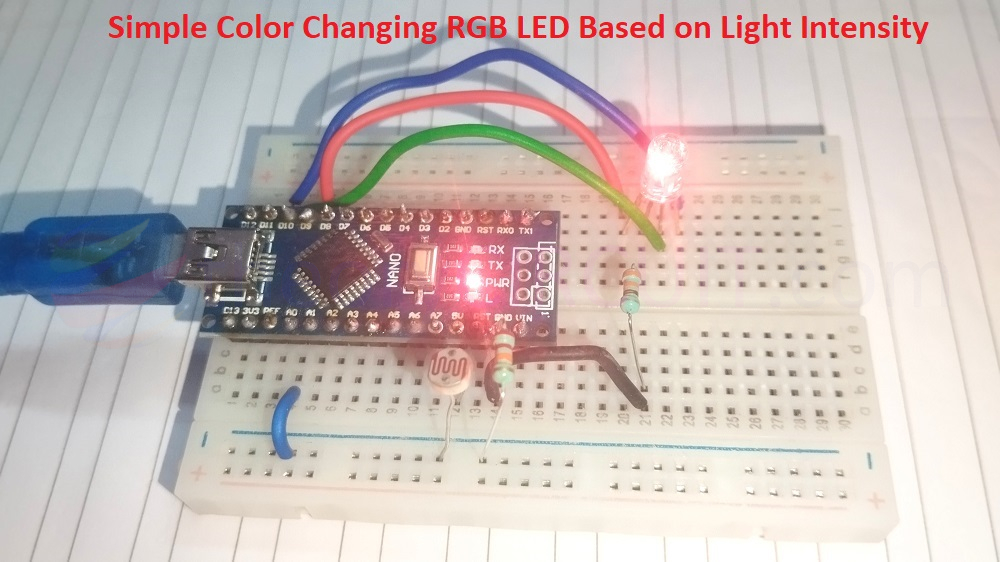
Simple and fun project for STEM learners, even a beginner can make this Simple Color Changing RGB LED Based on Light Intensity. Here we use LDR to measure the light intensity. You may know that LDR (Light Dependent Resistor) gives different range of Resistance between its terminals based on the light intensity. By measuring this value using Arduino board we can make RGB LED to react with different color output.
This simple and beginner friendly project requires few easily available components they are,
- Arduino Nano (or any other Arduino board)
- LDR (Light Dependent Resistor)
- RGB LED (Common Cathode)
- Resistors: 22KΩ, 330Ω
- Breadboard and jumper wires
- PC with Arduino IDE
Circuit Diagram
Working Video
Construction & Working
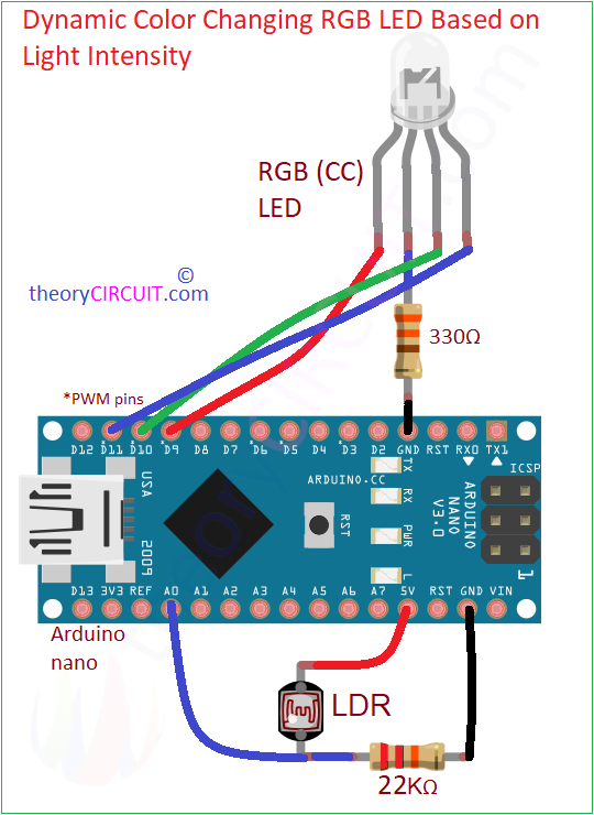
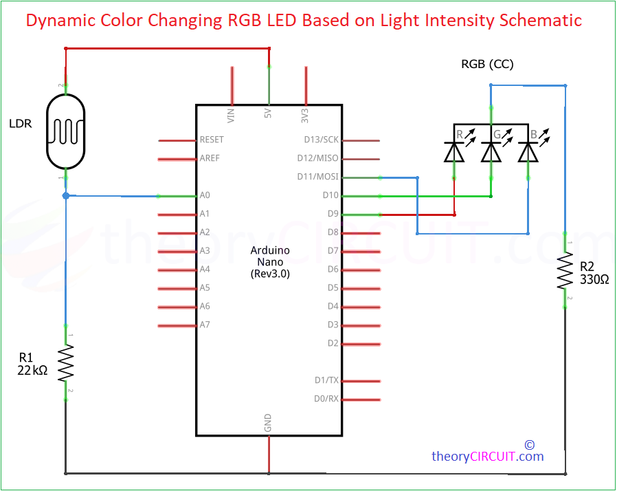
Here we used common cathode RGB LED and made code for that, The LDR and 22KΩ R1 Resistor forms voltage divider between bias (+5V, Gnd) then the Analog voltage output is taken from the junction between LDR & R1 then connected to A0 on the Arduino board. RGB LED’s cathode pin is connected to the GND through 330Ω Resistor, then individual pins RED (9), GREEN (10) and BLUE (11) are connected to PWM capable pins that is (9, 10, 11 of Arduino Nano board).
Now its time to make code,
// Pin Definitions
const int ldrPin = A0; // LDR connected to analog pin A0
const int redPin = 9;  // Red pin of RGB LED
const int greenPin = 10; // Green pin of RGB LED
const int bluePin = 11; // Blue pin of RGB LED

void setup() {
  // Initialize pins as output
  pinMode(redPin, OUTPUT);
  pinMode(greenPin, OUTPUT);
  pinMode(bluePin, OUTPUT);

  // Start Serial communication for debugging
  Serial.begin(9600);
}

void loop() {
  // Read the LDR value (0 to 1023)
  int ldrValue = analogRead(ldrPin);

  // Map LDR value to a range suitable for RGB (0 to 255)
  int redValue = map(ldrValue, 0, 1023, 0, 255);
  int greenValue = map(ldrValue, 0, 1023, 255, 0); // Inverse for green
  int blueValue = map(ldrValue, 0, 1023, 255, 0); // Inverse for blue

  // Write the RGB values to the LED
  analogWrite(redPin, redValue);
  analogWrite(greenPin, greenValue);
  analogWrite(bluePin, blueValue);

  // Add a small delay for smooth transition
  delay(10);
}
Here the LDR sense intensity of surrounding light and gives changes in Resistance, so the output voltage at the junction changes accordingly, Arduino reads the voltage through the Analog Pin A0 and converts it into a value between 0 to 1023.
In Arduino code map( ) function scales the LDR values into the range of 0 to 255, which is suitable for controlling the brightness of the colors in RGB LED, and this works as RED intensity increases as the light intensity decreases. GREEN and BLUE intensity decreases as the light intensity decreases, here this is inversely mapped. This simple project can be used in Ambient lighting applications.


