Last Updated on March 16, 2024
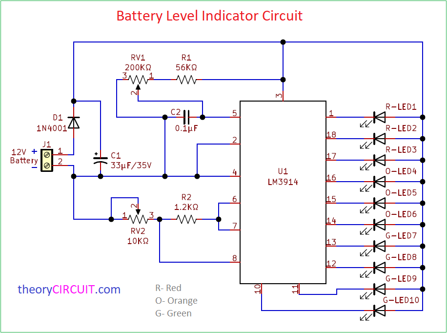
Simple Battery Level Indicator Circuit designed by using IC LM3914 – dot/bar display driver from Texas Instruments. This circuit detects battery charging level and indicates the percentage of charge through 5mm LEDs. First three Red LEDs are indicates 0 to 30 percentage battery, Orange Color LEDs are indicates 40 to 60 percentage battery level and Green LEDs are indicates 70 to 100 percentage charge level of battery.
This Battery Level Indicator Circuit designed to be employed in 12V battery environment. IC LM3914 is a monolithic Integrated circuit that senses Analog Voltage levels and drives 10 LEDs, and also Bar graph LEDs. This IC LM 3914 contains its own adjustable reference and accurate 10 step voltage divider.
Circuit Diagram
Components Required
| 1 | C1 | 33µF/35V | CP_Radial_D10.0mm_P5.00mm | 1 | ||
| 2 | C2 | 0.1µF | C_Disc_D3.0mm_W1.6mm_P2.50mm | 1 | ||
| 3 | R1 | 56KΩ | R_Axial_DIN0204_L3.6mm_D1.6mm_P5.08mm_Horizontal | 1 | ||
| 4 | R2 | 1.2KΩ | R_Axial_DIN0204_L3.6mm_D1.6mm_P5.08mm_Horizontal | 1 | ||
| 5 | D1 | 1N4001 | D_DO-41_SOD81_P7.62mm_Horizontal | 1 | ||
| 6 | U1-LM3914 | LM3914 | DIP-18_W7.62mm | 1 | ||
| 7 | G-LED7, G-LED8, G-LED9, G-LED10, O-LED4, O-LED5, O-LED6, R-LED1, R-LED2, R-LED3 | LED | LED_D5.0mm_Clear | 10 | ||
| 8 | RV1 | 200KΩ | Potentiometer_Bourns_3266W_Vertical | 1 | ||
| 9 | RV2 | 10KΩ | Potentiometer_Bourns_3266W_Vertical | 1 | ||
| 10 | J1 | 12V Battery | TerminalBlock_Altech_AK300-2_P5.00mm | 1 |
Features of LM3914
- It Can drive LEDs, LCDs or Vacuum fluorescents.
- Bar and dot display mode are externally selectable.
- It can operate with 3V supply.
- Output current programmable from 2mA to 30mA.
- Output from LM3914 can interface with TTL or CMOS logic.
Construction & Working
Indicator LEDs are connected to the corresponding output pin of LM3914 IC. In this circuit we used 18 pin PDIP package IC. Bias to this IC directly applied from the input battery. RV1 – Variable Resistor controls sensitivity of signal input and RV2 – Variable Resistor controls divider and Reference Adjust.
In this Battery level indicator circuit dot display single LM3914 driver configuration used hence the mode select pin (9) leaved as open circuit. If you want to connect 20 LEDs then you can use two LM3914 ICs together (Refer Datasheet)
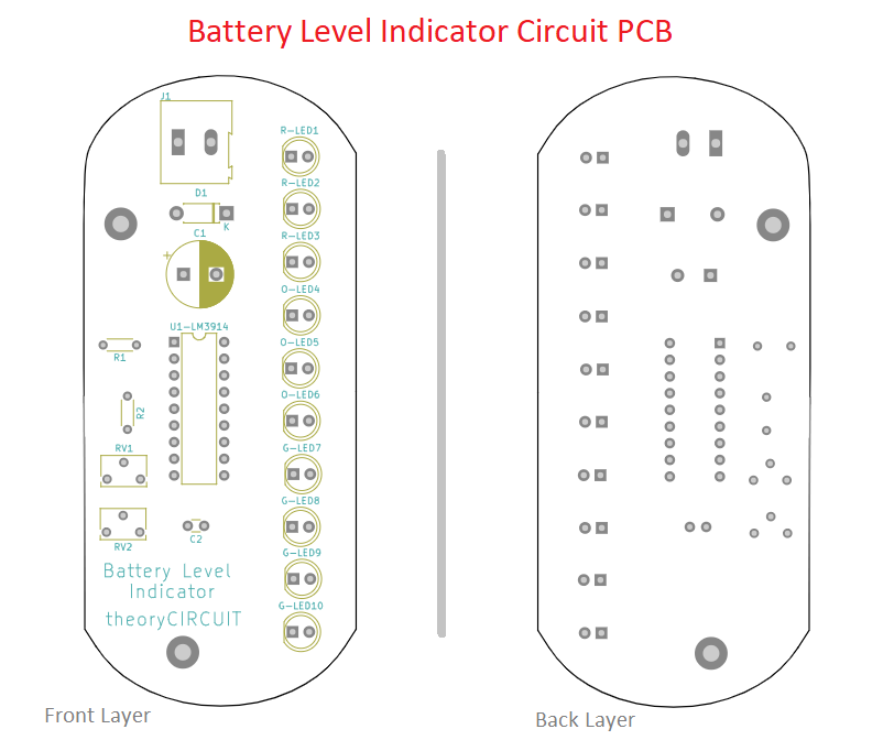
Printed Circuit Board
Battery Level Indicator Circuit PCB Gerber Files.
Interactive Board Viewer


I made a schematic as exactly as your schematic, but I am curious where the ground is. I think this is the reason why the input power is not driven.
Hi Hyoju kang
For LM3914 IC Pin 2 is Connected to Gnd ( Ground or Negayive ) terminal to the battery and we don’t need separate ground for this circuit.
Adjust RV1 and RV2 for calibration.