Last Updated on March 16, 2024
Smoke Exhaust fans are need to run when presence of smoke, but most exhaust fan runs without any use and increases electricity utilization, to avoid this situation Automatic smoke exhaust fan circuit developed with easily available components.
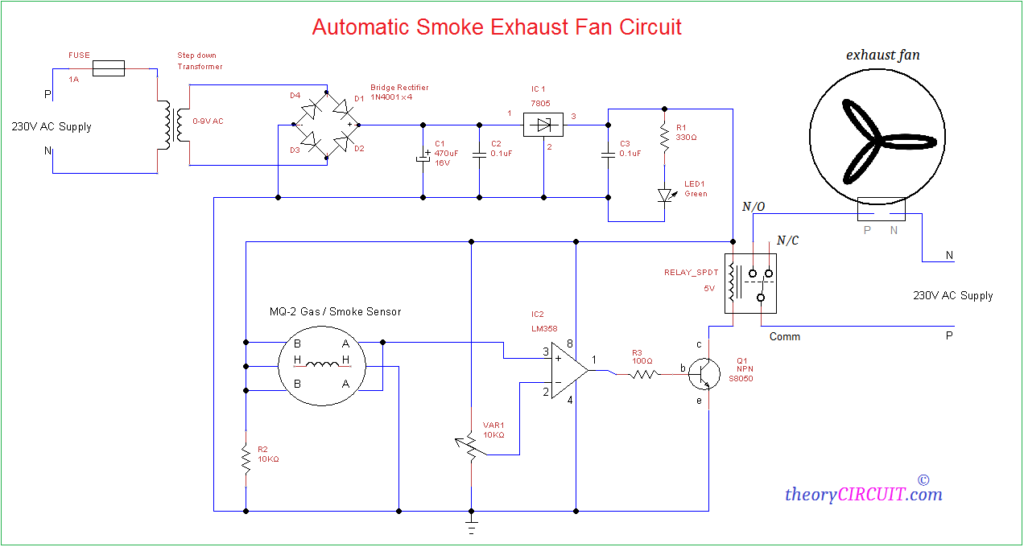
Here you can use the same exhaust fan and change the electrical wiring to the circuit relay and then it becomes automatic exhaust fan. MQ-2 Gas/Smoke sensor is used here to detect the smoke.
Circuit Diagram
Construction & Working
MQ-2 Sensor has good sensitivity to combustible gas and smoke, this sensor uses heating element to detect smoke and this sensor conductivity rises along with smoke or gas level rising. This sensor will have six terminals, two middle terminals are connected with inner heater component and others are terminal A and terminal B (sensing element).
230V AC to 5V DC
This circuit operates with 5V DC supply hence Rectifier and voltage regulator is used, 230V AC supply is step downed to 9V AC by using step down transformer, four 1N4001 diodes are employed to convert 9V AC supply into 9V DC supply, here 470μF C1 capacitor filters the AC ripples in rectified DC supply then positive voltage regulator IC 7805 employed to regulate the 9V DC into 5V DC supply. LED1 (Green) indicates the power supply status.
Sensor pin B, H, B are commonly connected to +5V supply and SPDT relay coil also connected with +5V supply. Two sensor terminals A, A are connected towards operational amplifier (LM358) non-inverting input. Another heater terminal H is grounded.
Variable Resistor VR1 connected between +5V DC supply and variable terminal connected with inverting input of op-amp. Here this op-amp configured as comparator circuit and the sensitivity of this circuit can be varied by VR1. Output of op-amp connected to the switching transistor Q1 (S8050) base terminal, this transistor acts as switch in the Relay coil terminal.
When there is no smoke the op-amp output will be near to 0 volt and the Q1 stays in cutoff or open state so the relay coil don’t get ground supply. If the smoke rising then the op-amp output will rise upto 4V and the Q1 becomes closed turn on or Active state so the relay coil gets ground supply then it becomes electromagnet.
When the relay coil gets energized then it attracts common lever to normally open contact and the supply flows through it, then exhaust fan runs automatically. Afterwards fan gets turned off automatically.
S8050 Pinout
This is a Three terminal NPN silicon transistor. S8050 is low voltage high current small signal NPN transistor, designed for Class B push-pull audio amplifier and general purpose applications.


is it working?
practically
Yes when Smoke hits the Sensor.