
Last Updated on March 16, 2024
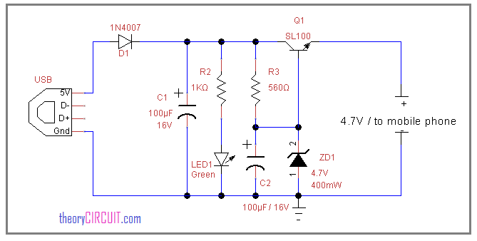
The USB power mobile charger circuit constructed by using zener diode (4.7V/400mW) and switching transistor SL100. before trying this circuit take extra care on mobile battery specifications.
The USB port (see more about USB here) gives DC bias from pin1 and pin4 that power supply regulated by using zener diode depends on the regulating voltage range. choose the zener diode as per the mobile battery specifications and requirements, at the end output pin gives regulated power supply.
[stextbox id=”alert”]Before trying this circuit take extra care in battery polarity and current rating, if anything goes wrong the battery might explode.[/stextbox]