Last Updated on March 16, 2024
Simple Field Strength Meter Circuit is designed by using single transistor and few easily available components. This circuit can be used to detect magnetic field strength of radio signal and common radio transmitting signal through antenna.
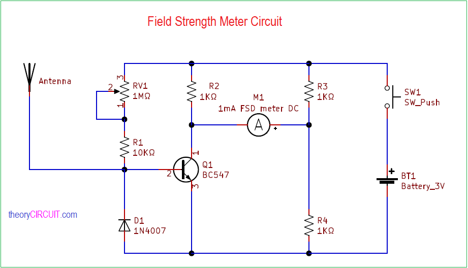
This field strength meter uses an 1mA FSD ammeter DC and indicates the radio magnetic field strength between 0 to 1mA scale range. This circuit help us to find the radio transmitting circuit working condition, this circuit can not be used to measure field strength accurately. If need to measure field strength for critical applications then use digital field strength meter.
Circuit Diagram
Components Required
- Transistor BC547 NPN – 1
- 1mA FSD ammeter DC – 1
- Diode 1N4007 – 1
- Push button switch – 1
- Resistor 10KΩ, variable resistor 1MΩ – each one
- Resistor 1KΩ – 3
- Battery 3V
- Antenna (Wire)
Construction & Working
Here we use only one transistor and few external components hence we can construct this circuit without complex steps, start with bias resistors to BC547 and place variable resistor RV1 in series with R1 connect Diode D1 to the base of transistor in reverse polarity and this will helps to eliminate reverse polarity signal from antenna.
Connect 1mA FSD ammeter DC between transistor collector and Voltage divider resistors R3 and R4, make sure to connect meter positive terminal to the voltage divider. Here whole circuit is powered by 3V battery you can use CR2025 coin battery or AAA battery to this circuit. A push button switch place in the power supply path and by pressing only we can measure the field strength.