Last Updated on March 16, 2024
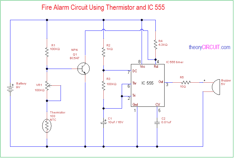
Simple Fire Alarm Circuit designed by using 10K NTC (Negative Temperature Coefficient) Thermistor and timer IC 555, this circuit will produce buzzer sound when the temperature near thermistor raises beyond threshold, and this threshold limit can be varied by using variable resistor.
This simple fire alarm circuit can be used as a indicator or warning circuit for excessive fire and temperature, you can connect relay at the output to connect or disconnect target device.
Circuit Diagram
Components Required
- Timer IC 555
- Thermistor 103, NTC
- Buzzer 5V
- Transistor BC547
- Variable Resistor 100KΩ
- Resistor 100KΩ = 2
- Resistor 1KΩ, 4.3KΩ, 10Ω each one
- Capacitor 10μF / 16V, 0.01μF each one
- Battery 9V
Construction & Working
In this fire alarm circuit we have used thermistor as a sensing element and this thermistor value is 10K and comes in NTC (Negative Temperature Coefficient) which means this thermistor Resistance across two terminals greatly reduced by heat.

In this circuit thermistor sensitivity level can be varied by VR1 and you need to calibrate according to your need. Timer IC 555 circuit Reset pin is connected with thermistor through transistor Q1 and IC 555 works as a Astable multivibrator.
When there is no fire and temperature rise near thermistor then timer IC 555 stays in Reset position. When the temperature rises timer IC 555 starts to oscillate square pulses and produce sound through buzzer element.
Note, this circuit sensing element thermistor should exposed to fire or temperature for proper working, if you want to built non contact fire alarm circuit then you can refer Arduino Flame sensor Interface.
This circuit recommended for only indoor and study purpose and not suitable for industry standard.
It is not working help me. It keeps on buzzing even if didnt sense fire.
Help me. It is not working