
Last Updated on March 16, 2024
There are So many darkness detector circuit available in the internet but the following Automatic Dark Detector Circuit will be reliable to use with 3mm LDR (Light Dependent Resistor). Darkness detector circuits are very useful across different applications like security system, Energy conservation, Outdoor lighting control and Automation etc.., following circuit offers cost effective and efficient way to detect darkness and gives beep sound alert. You can use electromagnetic relay or Semiconductor switch to extend the applications from just alert sound.
As we know main sensing element LDR’s Resistance Value between two terminal is depends on the intensity of light falls on it’s sensing surface. LDR or Photoresistors are typically made from photosensitive material cadmium sulfide (CdS) with other semiconductor materials formed as zig zag shape lines and transparent coating.
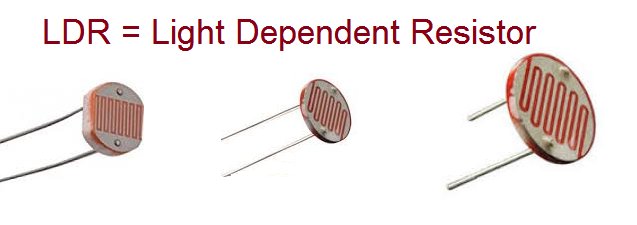
LDR comes in different size and Resistance range. Mostly LDR provides >2MΩ Resistance during darkness or light block and gives <few Ω to KΩ depends on the intensity of light falls above its sensing surface.
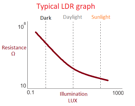
In this graph Y axis – Resistance Value between two terminal of typical LDR mentioned in ohms (Ω) and X axis – Light intensity level Illumination mentioned in LUX. You can choose different size and Resistance value LDR depends on your project and applications.
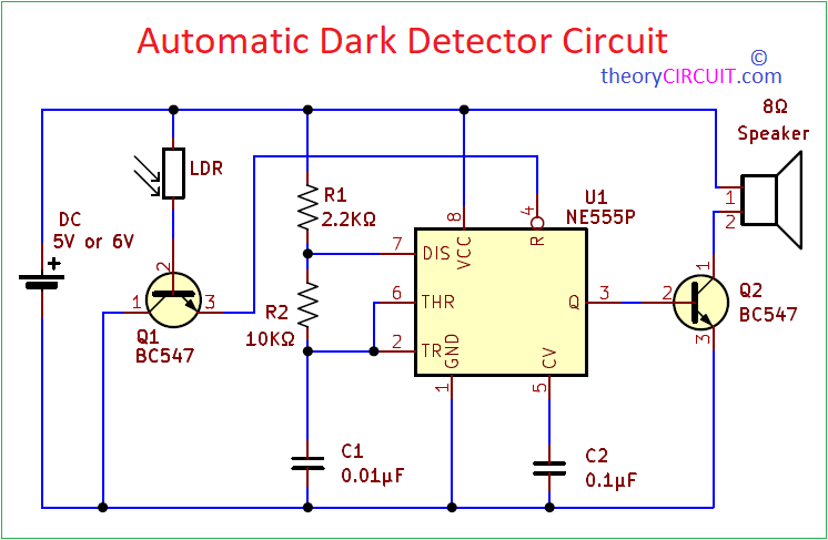
Circuit Diagram
Components List
- Timer IC NE555P
- Transistor BC547 = 2
- 8Ω Speaker
- LDR 3mm
- Resistors 2.2KΩ, 10KΩ each one
- Capacitors 0.01μF, 0.1μF each one
Construction & Working
Construction of this dark detector circuit starts with timer IC 555 and it is configured in Astable Multivibrator mode. To get the desired output frequency from IC 555 use Astable Multivibrator Calculator to Choose Timing Resistor and Timing Capacitor. After connecting R1, R2 and C1 output terminal is connected to the transistor Q2 base and Loud speaker is connected with positive supply then collector terminal of Q2. This Q2 acts as switch and also amplifier to the speaker. LDR is connected with the base terminal of Q1, collector terminal is connected with GND or -ve then Emitter terminal of Q1 is connected with Reset pin (4), here the Q1 acts as switch to control the Reset pin (4) of timer IC 555.
During the light fall LDR gives low Resistance and positive supply flows through it to the base terminal of Q1 so the Q1 conducts GND to the Reset pin. Due to GND to the Reset pin timer IC 555 stays in reset (off) position. Whenever the darkness appears to the LDR then it gives Very high resistance and blocks positive supply to the base terminal of Q1. So that transistor Q1 gets turn off and stays open. Open Reset pin is considered as HIGH input and then timer IC 555 starts to oscillate square pulse depends on the timing elements and drives speaker through output.
Shortage with Components?
If you are Shortage with Components, then try the following simple darkness detector circuit made by using single LDR and Single transistor with one buzzer.

Components List
- 3mm LDR
- Transistor BC547
- 6V Buzzer
- Resistor 220Ω
- Battery
Here LDR gives base input to the BC547 depends on the Light illumination and Transistor BC547 acts as a parallel switch to the buzzer. When the light falls on the LDR surface then the transistor gets base supply and stars conducts so the buzzer don’t get any supply (transistor short circuits buzzer terminals). If the darkness detected by the LDR then the base of BC547 don’t get bias through LDR due to high resistance and stays open (OFF) condition and Buzzer gets bias and gives alert beep sound.
Hello, can you provide me a possible PCB layout for the schematic diagram for PCB etching? Thanks!
Hi, I have assembled this circuit and it didn’t work. I found it weird the collector of the transistor hooked up to the LDR being connected to ground. Is it correct?