
Last Updated on April 28, 2024
A DIY Main Power Supply Failure Indicator Circuit designed by using few easily available components, Ensuring the reliability of power supplies is crucial in various electronic applications, ranging from consumer electronics to industrial systems. This simple circuit can help us to take appropriate action in case of power interrupt or failure.
Main purpose of this circuit is to alert us by giving audible beep sound when power failure occurs. Backup for the buzzer is Capacitor C2 and by using more Value like 2000μF, 3000μF (by connecting parallel capacitors) we can increase the duration of beep sound from buzzer.
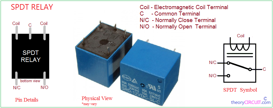
SPDT Relay Pinout
Switching element of this circuit is SPDT (Single-Pole Double-Throw) Relay and it operates with 9V DC supply. With its single Common terminal and two output terminals (Normally Open and Normally Close), an SPDT relay can control a circuit by selectively connecting the common terminal to either of the two other terminals, effectively toggling between two different circuits.
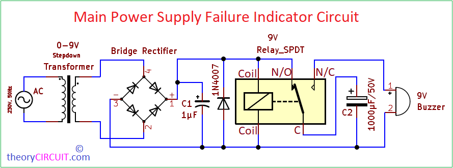
Circuit Diagram
Components List
- Stepdown Transformer 0-9V / 500mA
- Bridge Rectifier Module W10M or Four 1N4007 Diodes
- Electrolytic Capacitors 1μF/16V, 1000μF/50V each one
- Diode 1N4007
- 9V SPDT Relay
- 9V Buzzer
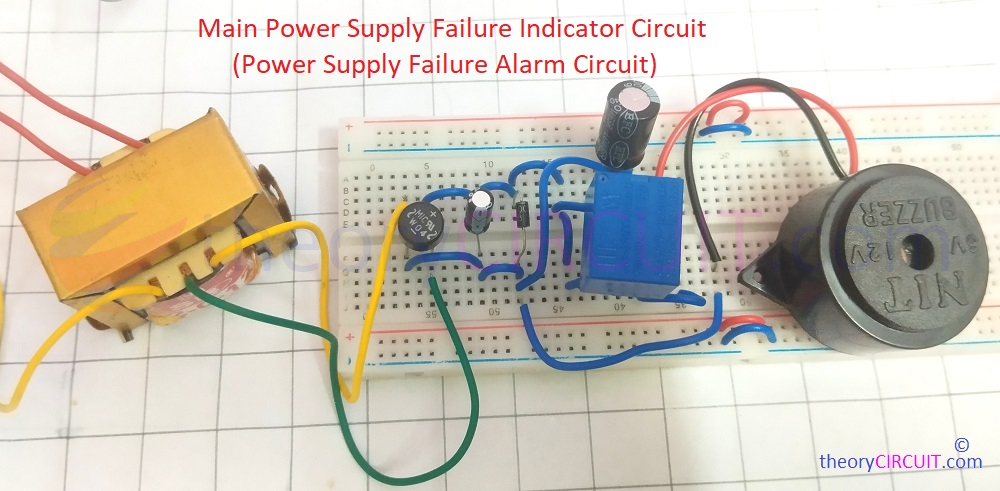
Working Video
Construction & Working
Construct the circuit in a common pcb board by following the given schematic and check all connections for accuracy and solder quality then Connect the primary terminals of stepdown transformer to the main power supply you want to monitor. Apply power to the circuit and verify its operation. When the main power supply is functioning correctly, the relay remains inactive (Charges Capacitor C2), and the buzzer remains silent. In the event of a power failure, the relay switches to Normally Close and activating the buzzer to indicate the failure.
Here the Transformer steps down the AC Supply (230V, 50Hz) to a safer level 0-9Vac and the bridge rectifier converts the AC voltage into DC, ensuring a constant polarity output. You can use either a Bridge Rectifier Module (W10M) or four 1N4007 diodes configured in a bridge rectifier. 1μF capacitor acts as a filter capacitor for filtering AC ripple noise from the DC supply. The 9V SPDT (Single Pole Double Throw) relay is used to connect the C2 Capacitor with DC during main power supply presence and connects the buzzer and C2 Capacitor positive terminal during power failure. 1N4007 diode is connected in parallel to the relay coil to suppress back EMF when the relay switches.
Improvements
Here is some improvement for above circuit, During the main power failure or interrupt, the capacitor C2 charge is initially discharge through Relay Coil and after the charge in C2 decrease certain level (not enough for magnetizing relay coil) then the relay coil release the lever makes contact with N/C (normally close) contact and buzzer gets remaining charge from C2 to make alert sound. To avoid this problem we have to introduce a discharge blocking diode (1N4007) in the above circuit.
Improved Main Power supply Failure Indicator Circuit
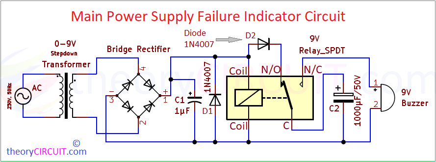
As you can see this Power Supply Failure Alarm Circuit have Diode D2 in between positive supply line and N/O (Normally Open) Contact. Due to Reverse bias from C2 to Relay coil, it blocks the charge from capacitor C2 to Relay coil. So the Buzzer gets full charge from C2 and makes Louder and Longer Alert sound (Buzzer beep Sound).