Last Updated on March 29, 2024
Traffic signal lights are very Important to regulate vehicles and traffic on roads, simple four way traffic light circuit is designed with timer IC 555 and counter IC CD4017. we know each traffic signal light setup will have three colors and representing Red for STOP, Yellow for WAIT, and Green for GO, those signals are works based on time intervals.
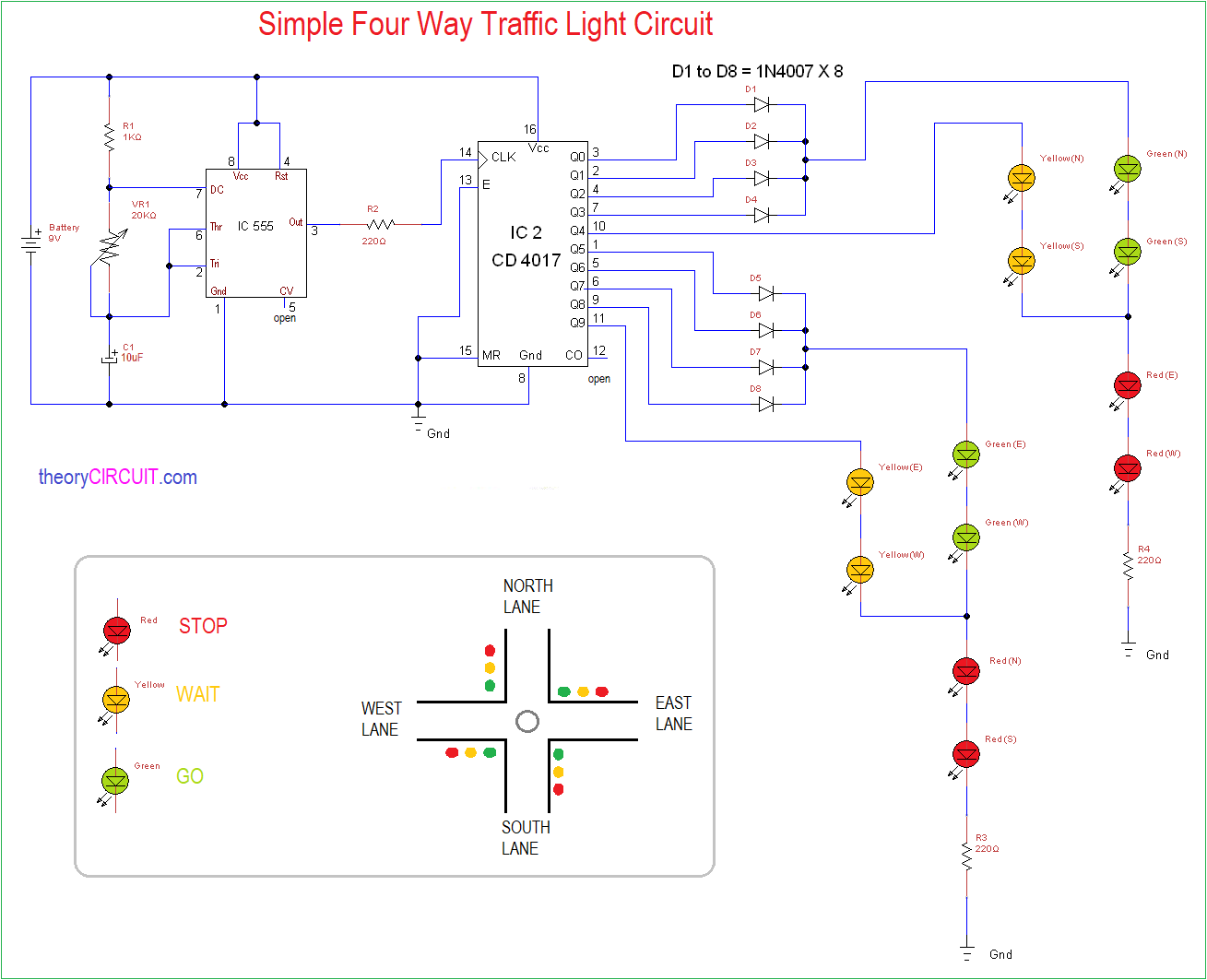
In this simple four way traffic light circuit we have used timer IC 555 as astable multivibrator to produce pulse based on timing Resistor and timing Capacitor, then output pulse from IC 555 is fed into counter IC CD4017 clock input this counter integrated circuit counts pulse and changes the output line (Q) logic into HIGH or LOW, by connecting proper color LED at this counter IC output, we can obtain traffic signal light.
Circuit Diagram
Components Required
- Timer IC 555
- Counter IC CD4017
- Diode 1N4007 X 8 Nos.
- LED Green 4 Nos.
- LED Yellow 4 Nos.
- LED Red 4 Nos.
- Resistor 1 KΩ = 1, 220Ω = 3.
- Variable Resistor 20KΩ.
- Capacitor 10μF.
- Battery 9V.
Construction & Working
This simple four way traffic light circuit has two stage one is timing & counting stage another one is Indication lights stage. Those indication lights are should be properly placed on four lanes. Here timer IC 555 placed with timing Resistor R1, VR1 and timing Capacitor C1 based on these elements value output pulse delivered at output pin. These pulse are decides the timing interval of traffic light signals.

For this equation RA = R1, RB = VR1 and C = C1.
Output pulse from timer IC is fed into Counter IC CD4017 clock input through R2 Resistor. Counter IC output Q0 to Q3 will drive Green signal for North & South Lane, Red signal for East & West Lane. Output Q4 drives Yellow signal for North & South Lane.
Output Q5 to Q8 will drive Green signal for East & West Lane, Red signal for North & South Lane. Output Q9 drives Yellow signal for East & West Lane.


nice tip …am puting it to work,, will get back to you
Produced a PCB and ciruit of this. Works well, nice job!
Lucy,
Could you send me circuit file you created and tips for PCB ?
Sir I made different type of traffic light where sancer which are using the circuit
What is the voltage rating of capacitor
i appreciate ur idea
Did you do the simulation on proteus? was trying it but LED are not lighting
SIR which type of flip flop is used in it
Hi muaz saleem,
Texas Instruments Cd4017 is a Decade Counter with 10 Decoded output. Internally CD4017 uses five D flip flop.