Last Updated on March 16, 2024
We know the nickel–cadmium battery is called as NiCd battery or NiCad battery and this types of rechargeable batteries are made with nickel oxide hydroxide and metallic cadmium as electrodes. NiCd batteries provides better performance in compact size. Hence it is widely used in hand held and compact electronic devices. Simple NiCd Battery charger circuit made with few easily available components.
The following NiCd Battery charger circuit can be used for charging individual battery or battery bank. This circuit will provide limited current and voltage to the target battery.
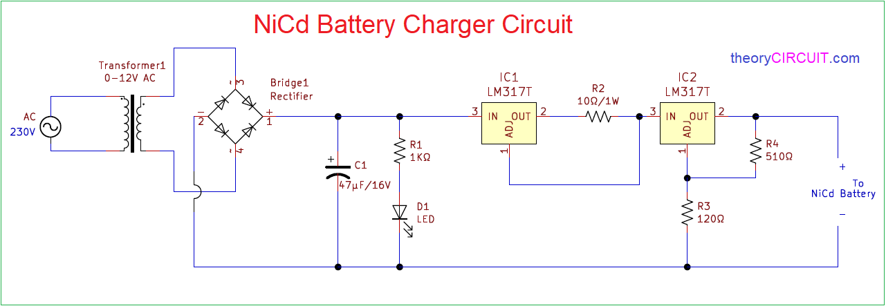
Circuit Diagram
Components Required
- Step down transformer (0-12V AC)
- Bridge Rectifier Module or (1N4007 X 4)
- Regulator IC LM317 = 2
- Resistors 1KΩ, 120Ω, 510Ω each one
- Resistor 10Ω/1W
- Capacitor 47µ/16V
- LED
Construction & Working
To construct NiCd Battery charger circuit start with step down transformer and connect Bridge Rectifier module or Four 1N4007 diodes in bridge connection. Then use Capacitor to filter Rectified DC supply and LED1 Indicates the presence of DC power supply, apply positive supply to the Regulator IC1 here the Adj terminal of the IC1 is connected at the output terminal followed by R2 Resistor and hence it provides constant current regulation.
Then IC2 Provides Regulated output voltage at the Out terminal here the output voltage is depends on the R3 and R4 Resistors value, you can change these resistors value depends on your requirement and use IC LM317 data sheet for exact resistor value calculation.
NiCd Battery
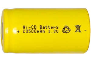
Here is the target Ni-Cd battery for our recharge circuit is shown and this battery provides 1.2 Volt with 3500mAh.
The second regulator is unnecessary. The output voltage of a constant current circuit will automatically adjust itself depending on the load. Assuming that there’s sufficient voltage available to drive the required current through the load (i.e., the circuit’s “compliance” is adequate), you can connect any load (even a short circuit) to a constant current generator, and only the programmed current will flow through it.
I disagree with Mr. Holmes, respectfully. Charging can be excessively high if not done properly and in that case the battery voltage will rise well above the correct level and the battery will be destroyed. I have witnessed this myself when someone tried to charge a 9V battery at 5mA constant current. In a couple of hours the battery made a rude noise and expired. The voltage regulator is necessary.
Hello
I am confusing about charging !
Witch one is right?
1- limited current fist then limited voltage ?
or 2- limited voltage then limited current?
how can sure voltage limiter R3 an R4 (in mode 1) not effect on current of battery?
can you publish this circuit with BJT transistor?
Thanks Armen
Hi Those are feedback elements Required for LM317 IC. These controls current and voltage flow from the charging circuit and not the battery.