
Last Updated on March 16, 2024
In digital electronics memory and memory cell circuit plays an important role. Now a days every electronic gadgets has gigabytes of internal and external memory. Some schematic utilize I2C EEPROM or flash memory ICs. In this article one bit memory circuit is developed by using timer IC 555 and RS NAND latch example given for better understanding of one bit memory cell.
We know one flip flop can store one bit status by the way we can store more bits by increasing number of flip flops we can use these kind of memory cells in digital circuits, Analog electronic circuits and hobby circuits we can also use 4 bit or 8 bit memory cells as a electronic lock.
Different types of memory cell and memory elements are available we are not jumping in that topic here. We are going to design and test one bit memory circuit using IC 555. Before that what is one bit memory cell? answer is, the memory cell is an electronic circuit that can store (state) logic high (1) or logic low (0) in binary form. If the size of memory cell increase greater than one then it must have address lines and some more memory will have chip select, enable etc..,

RS NAND Latch
We can create one bit memory by using two logic NAND gates.
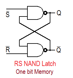
Here when both inputs are given as logic 0 the output goes to undefined (Q, Q’) and the both inputs are given as logic 1 the output remains no change. When S’ or Set pin given as logic 0 and R’ as logic 1 will provide output as Q=1 and Q’=0 this is known as set condition and this output don’t change upto return of S’ to logic 1.
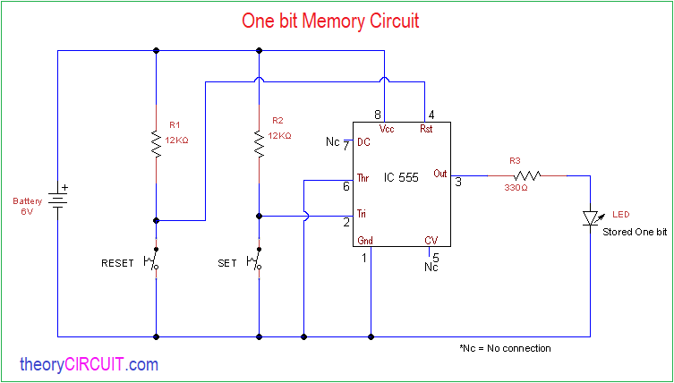
Circuit Diagram
Components Required
- IC 555
- Resistor 12KΩ = 2
- Resistor 330Ω = 1
- LED
- Push button = 2
- battery 6V
- bread board, hookup wires
Construction & Working
In this circuit Reset pin and trigger pin connected to ground supply through push button switch, when the push button pressed ground supply flow to corresponding pin. Threshold pin is directly connected to the ground and output pin is connected with LED to show the stored bit. If the LED glows then it represents logic 1, If it is in off condition then it represents logic 0.
When the set button pressed logic 1 bit is stored in IC 555 internal flip flop. When the Reset button pressed logic 0 bit is stored in IC 555 internal flip flop.