
Last Updated on March 29, 2024
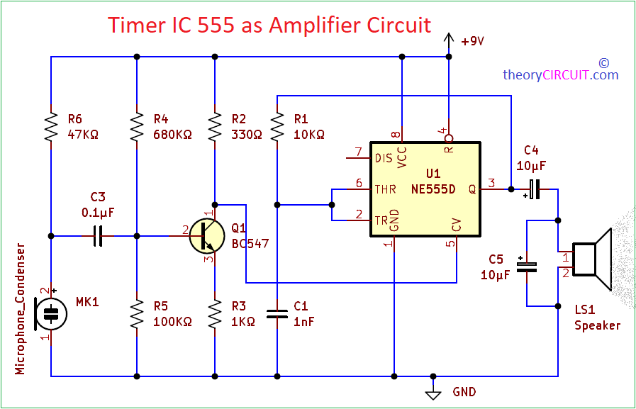
The 555 timer IC is a versatile integrated circuit commonly used for various applications, When configured appropriately, the 555 timer can function as an Astable multivibrator, a Monostable multivibrator, and even as a voltage-controlled oscillator. This experiment is to use Timer IC 555 as Amplifier, Here condenser Mic used to pic voice input and pre-amplified by Transistor BC547 then Amplified by Internal upper comparator of timer IC. However, using 555 as an amplifier requires a specific configuration. This circuit tried out as experiment and it has lot of limitation for amplifying the audio signal in terms of frequency, bandwidth and power output. For low-frequency applications and moderate amplification requirements, this configuration can be suitable.
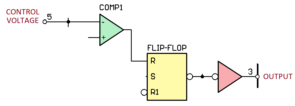
Internal Structure of Timer IC 555
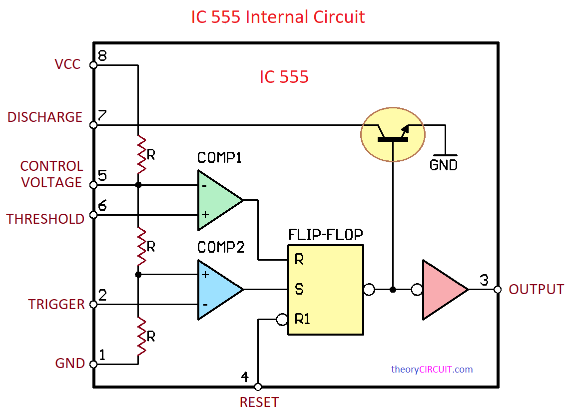
To understand the operation of 555 as amplifier, we need to look into internal structure of timer IC, In its basic form 555 timer consists of two voltage comparators, an SR flip-flop, a discharge transistor, and a resistor divider network. The voltage comparators monitor the voltage levels at the threshold (pin 6) and trigger (pin 2) inputs, comparing them to a reference voltage derived from the resistor divider network. Here Control Voltage Input pin 5 of the IC is an important input that allows external voltage control of the threshold and trigger levels. When the voltage at the trigger pin falls below 1/3 of the supply voltage, the output flips, setting the flip-flop and turning ON the discharge transistor. Conversely, when the voltage at the threshold pin rises above 2/3 of the supply voltage, the flip-flop is reset, and the discharge transistor turns OFF. This configuration allows the 555 timer to operate in various modes, including Astable, Monostable, and Bistable, making it an essential building block in electronic circuits, timers, pulse generators, and oscillators.
Circuit Diagram
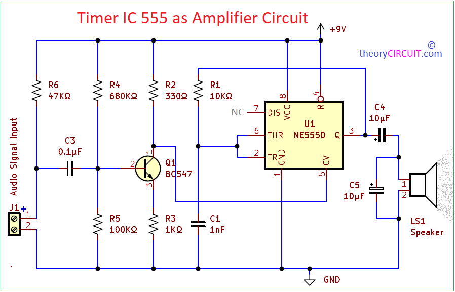
Circuit for Direct Audio Input
Components Required
| S.No | Name | Quantity |
| 1. | IC 555 | 1 |
| 2. | Loudspeaker 8Ω | 1 |
| 3. | Condenser Mic | 1 |
| 4. | Transistor BC547 | 1 |
| 5. | Resistor 47KΩ 680KΩ 100KΩ 1KΩ 10KΩ 330Ω | 1 1 1 1 1 1 |
| 5. | Capacitor 0.1uF 1 nF 10uF | 1 1 2 |
Construction & Working
Here the Amplifier circuit using IC 555 configured in Astable mode without Discharge pin connection, hence there is no discharge function through internal transistor. Pre amplified audio signal from source is applied to the control voltage pin.
By applying an external voltage to the Control Voltage pin, you can modulate the internal reference voltages of the 555 timer. This external voltage overrides the internal voltage divider network and directly influences the timing of the 555 timer that is output pulse width changes. When an external voltage is applied to the CV pin, it affects both the threshold and trigger levels proportionally. This feature allows for more precise control over the timing characteristics of the 555 timer circuit.
Here without any audio input there is no voltage at pin 5 and timer produce pulse frequency above 60KHz which will not reproduced as sound by loud speaker. When there is audio signal then pin 5 of timer receives some voltage and changes the output pulse width. This modulated pulse width signal can be reproduced as sound by the loud speaker.
About Condenser Microphone
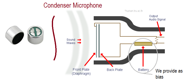
Few lines to explain how the condenser mic works, as we know a condenser microphone consists of a diaphragm (front plate) placed close to a backplate, These two plates placed to leaving a small gap between them but not touch each other. These diaphragm and the backplate are made from conductive materials and the air gap between them is acts as the insulator, this setup makes a capacitor. When sound waves hit the diaphragm, it vibrates depends on the acoustic wave, causing the distance between the diaphragm and the backplate to change. This movement of the diaphragm changes the capacitance value between the diaphragm and the backplate. This character helps to convert sound wave into electric audio signal. Output audio signal from this mic is very low in amplitude, hence it is necessary to make pre amplification.
Condenser microphone converts sound wave into electric audio signal and Transistor BC547 pre amplifier improves signal strength and Control voltage pin receives audio signal from transistor collector terminal, Voltage level of this signal varies depends on the audio signal amplitude and the output pulse width changes depends on the input audio signal. Here output amplitude will be 1/2 level of VCC applied to the timer IC, so you can use 9V to 15V DC as bias.