Last Updated on May 7, 2024
In today’s world we mostly depend on electric energy for day to day life. Having a backup power source is crucial, Power banks and Inverters helps us during the power supply outages. Inverter circuits are provides AC power output using available DC voltage from battery, some times we need low power output enough to drive a small electric light bulb or something those are not require pure AC power. Here a Simple Inverter Circuit using CD4047 and ULN2003 project design to avoid complex pure sine wave inverter and PWM inverter for the low voltage applications.
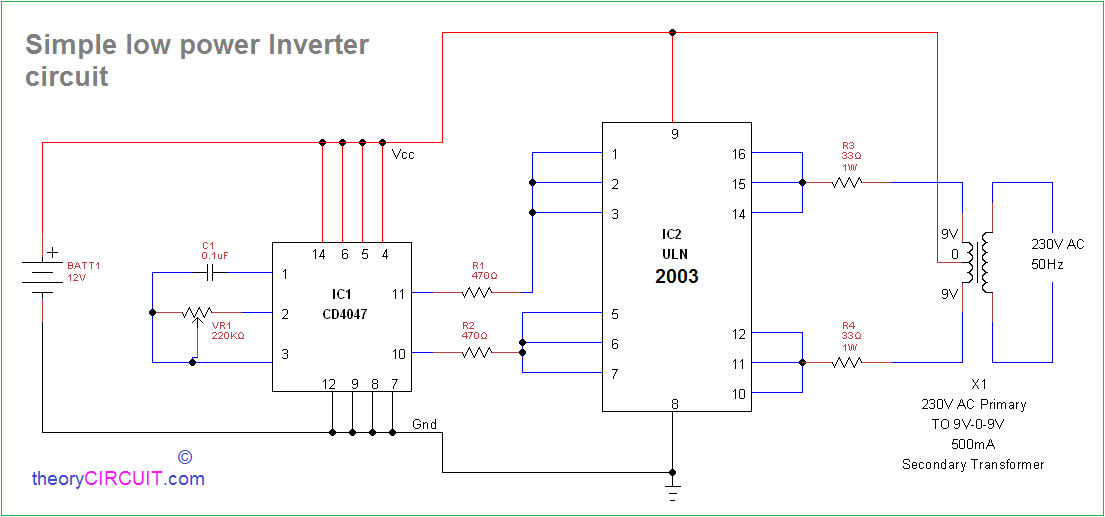
This Inverter Circuit using CD4047 and ULN2003 Oscillates Square pulse at desired frequency, and the driver amplifies the signal to drive the primary winding of the transformer (Here inverted normal stepdown transformer Secondary winding used as primary). The transformer steps up the voltage from the low input to the desired output.
Circuit Diagram
Construction & Working
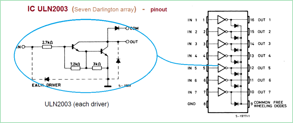
This circuit constructed in three simple stages, the first one is Multivibrator stage by using IC CD4047, it produce free running astable pulse with high peak voltages, and then second stage is power switching stage using IC ULN2003 (Seven Darlington array) it handles 500mA current and best suitable for inductive load driving. Here group of three channels connected in (Q bar pin 11) and (Q pin 10) output of CD4047. Output from ULN2003 connected to the transformer X1 secondary winding (9V – 0 – 9V) the center tapped pin is connected to the 12V supply. Transformer primary winding provides stepup Pulsating AC (load is connected between the primary winding terminals).
By varying the VR1 Resistor value we can change the frequency and voltage range of output AC supply, for to simplify the design there is no Switch, Fuse and MOV (metal oxide varistor) and this circuit involved in producing high AC Voltage that may give lethal shock so handle with extreme care.
IC ULN2003 Pinout
Datasheet
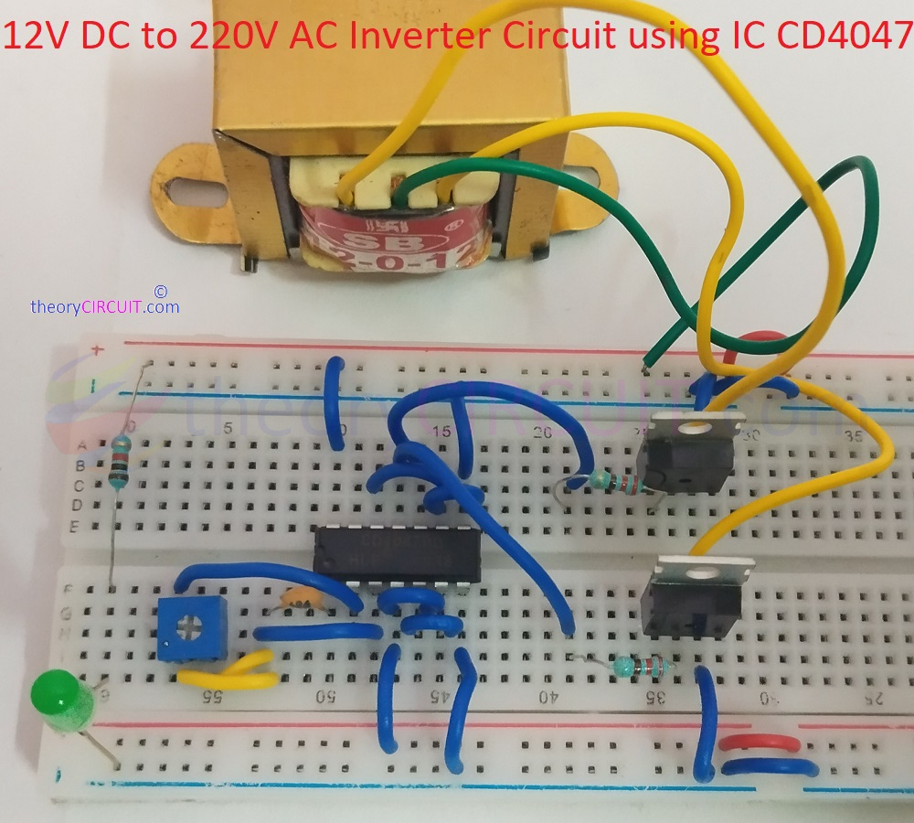
Similar Inverter Circuit using CD4047


