Last Updated on March 16, 2024
Pulse Width Modulation circuit or Pulse Duration Modulation circuit does the same work that is reducing the average power of transmitting electrical signal by separating signal into discrete samples. Pulse Width Modulation technique is used to Vary the width of Square pulse to represent the amplitude of input analog signal. The PWM signal has lot of advantages and applications in telecommunication, servo motor controlling, voltage regulation, motor speed control and digital circuits etc..,
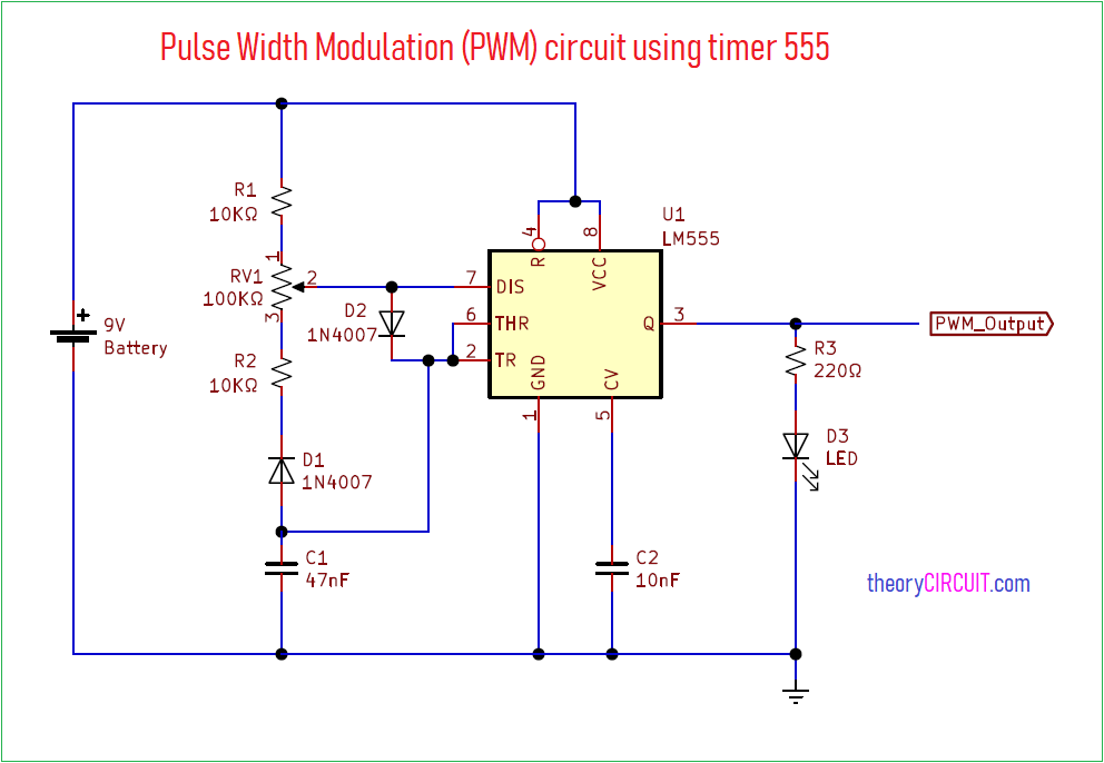
Here simple and useful pulse width modulation circuit designed with familiar timer IC 555, this PWM circuit produce continuous PWM signal without any input and output frequency range can varied by the variable resistor.
Circuit Diagram
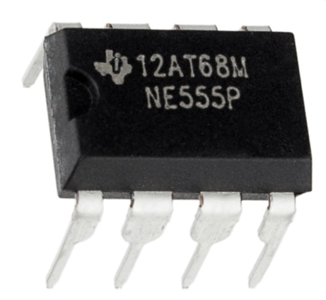
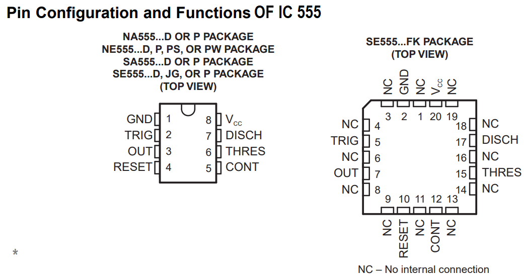
IC 555
Components Required
Construction & Working
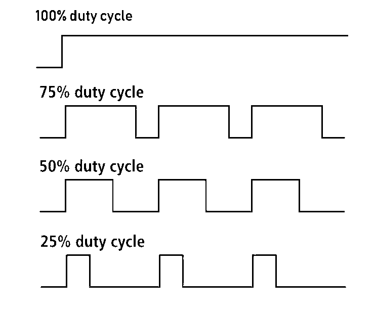
This Pulse width modulation circuit using timer IC 555 designed to deliver PWM signal at output with different level of duty cycle. Here IC 555 configured in astable multivibrator mode and output PWM obtained for continuous square pulse.
PWM (Pulse Width Modulation)
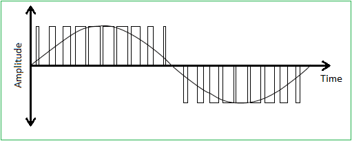
Width of Pulse is varies according to the amplitude of input signal, when the amplitude reaches the highest value then pulse duty cycle increases to maximum level by the way when the input signal amplitude reaches the lowest point then pulse width decreases to minimum level.
By varying the timer element RV1 we can change the pulse width modulation output frequency, here the LED indicates the duty cycle of output PWM with fading effect.
This circuit can be used in different PWM required places like LED driver, Servo motor driver, Micro controllers and Integrated circuits etc..,