Last Updated on March 16, 2024
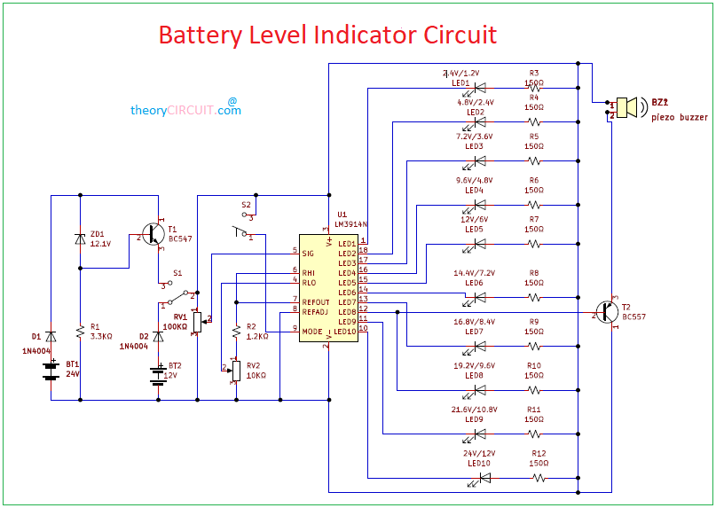
The LM3916 is a monolithic integrated circuit used as a dot/bar display divider. It specializes in sensing various levels of Analog voltages to operate ten LEDs. The current flowing through these LEDs is so programmable and regulated that it by passes the use of current limiting resistor in series with LEDs.
This voltage ranges from a low value of 3V to a high as 25V. The voltage reference used in IC is easily adjustable. the input signal from 0-1.5V of positive DC is made acceptable by the use of a high impedance input buffer.
Circuit Diagram
BOM
| S no | Designator | Value | Quantity |
| 1 | IC | LM3914 | 1 |
| 2 | BT1 | 24V | 1 |
| BT2 | 12V | 1 | |
| 3 | D1 | 1N4004 | 2 |
| ZD1 | 12.1V | 1 | |
| 4 | T1 | BC 547 | 1 |
| T2 | BC 557 | 1 | |
| 5 | S1,S2 | 2 | |
| 6 | VR1 | 100KΩ | 1 |
| VR2 | 10KΩ | 1 | |
| 7 | R1 | 3.3KΩ | 1 |
| R2 | 1.2KΩ | 1 | |
| R3,R4,R5,R6,R7,R8,R9,R11,R12 | 150Ω | 10 | |
| 8 | LED1 TO LED10 | 10 | |
| 9 | PZ1 | 1 |
Construction and Working
The LEDs are connected to pin no 1 and pin 10-18 as shown above. The higher end of the divider pin no 6 is connected to an external resistor and reference adjustment at pin 8. The lower end of divider pin no 4 is grounded. The current flowing out of the pin no 7determines the brightness of LEDs. The current flowing through each LED while glowing is around ten times greater than the current flowing out of the reference out pin no 7. An internal voltage reference of 1.25V is applied to the string of resistor. As the input voltage change from 0-1.25V, the output of comparator is set to low one by one thus flowing on the LEDs.
The input signal ranging from 1-12V is applied pin no 5 as an input to the high input impedance buffer. The mode pin no 9 selects mode as bar graph or dot display. For bar graph display pin no 9 is directly connected to pin no 3 while pin no 9 is kept open circuit for selecting dot display.
pin no 9 is a mode selection pin that is used to select either dot mode or bar mode. Make a connection according to these criteria to select either mode.