Last Updated on March 16, 2024
We count everything, in order to project or show the count value we need number display and here simple seven segment counter circuit designed to show the count value in single digit seven segment LED display. This circuit will show and increase the number digit when the count key pressed.
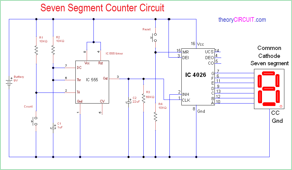
This simple seven segment counter circuit build with timer IC 555 and Decade counter IC 4026 and then common cathode type seven segment LED. Here timer IC 555 works as a Monostable multivibrator and produce single pulse when the count key pressed. Decade counter IC 4026 receives pulse as a clock and counts each clock then drives seven segment LED to show the number.
Circuit Diagram
Components Required
- IC 555
- IC 4026
- CC Seven segment LED
- Resistor 10KΩ = 3
- Resistor 68KΩ
- Capacitor 1μF, 22μF each one
- Push button switch = 2
- 9V Battery
Construction & Working
Here the timer IC 555 configured as monostable multivibrator and a Push button switch is connected to Trigger pin to give negative trigger input, depends on the timing Resistor R2 and timing Capacitor C1 timer IC produce Monostable Pulse. Capacitor C2 and Resistor R3 gives balance bias to monostable pulse and then decade counter IC 4026 receives pulse through Clock input pin 1. Each pulse increases the count value of IC 4026 and gives seven segment numerical output to drive Seven segment LED (Here we have used Common Cathode type Seven Segment LED display).
You can Reset the count value by pressing Reset push button or it will repeat 0 to 9 count in ascending order for each clock input.
IC 4026 Pin Configuration
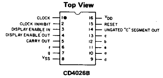
IC CD4026B CMOS Decade Counter consist of 5 stage Johnson decade counter and an output decoder which converts the decade counter output to 7 segment output. This IC will provide Carry out (C0) for next digit seven segment and Reset input.
Seven Segment Display
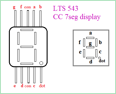
This Seven Segment Display LTS543 is a Common Cathode 7 segment display and it has segment input a,b,c,d,e,f,g and dot.
My confusion pertains to the capacitors. Your component list states 1uF , 22uF each ..
What am I missing? I only see a total of 2 capacitors.
Article says each one capacitors 1uF = 1 and 22uF = 1. Yes there are two capacitors only.
So for reset 4026 , you are short-circuiting which is totally wrong, just put a resistor of 22k between MR and reset botton
How much watt of capacitor and resistor I have to use