Last Updated on March 16, 2024
We use lot of digital gadgets in our daily life and we know every electronic gadgets needs power source to get charge, when we are in travel or some where in remote location our first fear will will be about the smartphone battery level. The following solar power bank circuit design avoids those hassles and we can charge our mobile or electronic gadgets when ever we want.
This solar power bank circuit provides DC power through USB connector and has 1 Watt white LED for lighting needs. This power bank circuit can be built with easily available breakout board.
Block diagram
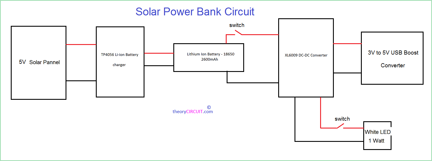
This block diagram describes about the power bank design. First one is 5V, 500mA solar panel then Li-Ion battery charger breakout board TP4056 then two lithium Ion battery 18650. Then at the output stage XL6009 DC-DC boost converter increases DC voltage range, 1 Watt white LED connected to XL6009 board output through toggle switch, finally 3V to 5V USB boost converter breakout board deliver power to mobile or gadgets.
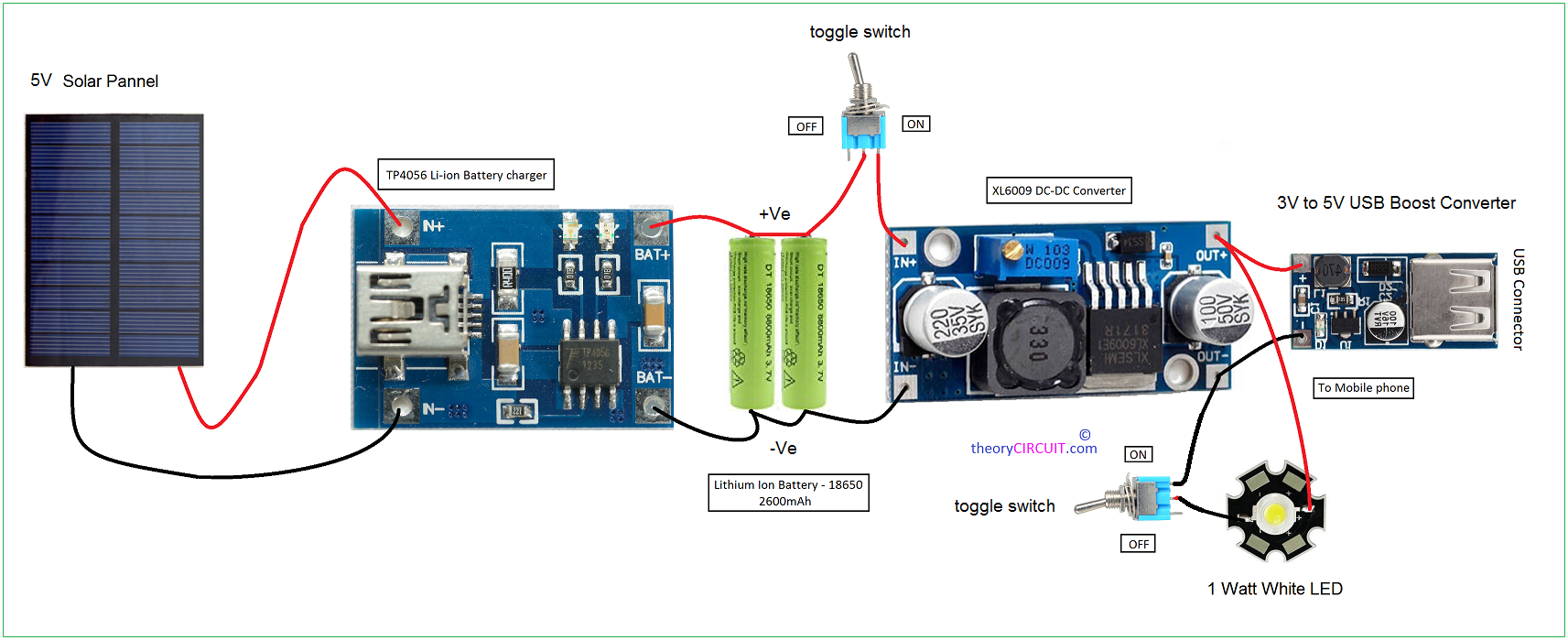
Circuit diagram
Construction & Working
Wiring the solar panel and other breakout board in this circuit is very simple. First connect the solar panel +Ve line to TP4056 Li-Ion battery charger board IN+ terminal and connect -Ve from solar panel to IN- of TP4056 board, two lithium ion battery connected in parallel and then terminals are connected to the BAT+ & BAT- of TP4056 battery charger breakout board.
XL6009 DC-DC converter is capable of giving 5V to 35V output from 3V to 32V input and then gives Non-Isolated boost output. This board connected to the Li-Ion battery through a toggle switch at the output of XL 6009 breakout board, 1 watt white LED and 3V to 5V USB boost converter are connected.
When the solar panel exposes to the sun light it will produce voltage through photovoltaic reaction and then the boosted voltage from TP4056 makes Li-Ion battery to charge. This charge can be converted into required voltage by XL6009 and USB boost converter breakout boards.
Note:-
[stextbox id=’info’]Test the polarity, output voltage and current at each breakout board and tune depends on your requirements. [/stextbox]
how much voltage is by the source?
what type of solar panel and how much capacity?
for how long does take to charge a phone?
please help
It depends on solar panel datasheet provided from the manufacturer.
and in this it is given as 5v.
capacity is 2.5watts.
Lion cells needs a protection IC, there are TP4056 boards with built-in DW01, use that instead.
The USB DC-DC converter will be more efficient when connected to the battery instead of being after the boost converter.
The TP4056 default charge rate is also 1A, either get a larger solar pannel or reduce the charge rate by modifying the resistor as per datasheet.
do you have any link where we can see all that you have described here?
How much the output charge from the usb to mobile
Can I connect 2 solar panels (2x 5,5 V 0,4 W) to this system and change nothing?
why do we need a toggle between battery and XL6009?
and if the switch is toggled, then will the power obtained at the output be direct solar -> output? ,
or will it be solar-> battery -> output?
kindly mention cost price for the boards
venktaraman