Last Updated on March 16, 2024
This circuit can be used to detect the RF signal and electromagnetic noise signal. These RF interference signal may produced by several electrical and induction appliances, if you are designing RF based circuit means you need to protect your design from these noise.
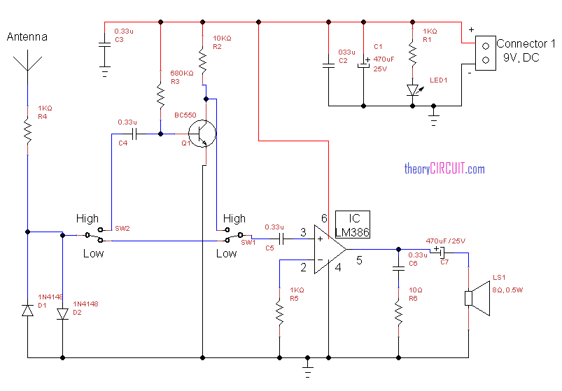
Circuit diagram for RF signal detector
To identify the presence of RF signal noise this circuit helps a lot.
Construction and Working
This circuit constructed with LM386 operational amplifier with transistor pre-amplifier using BC550, if you want to detect high frequency RF noise means you should pre-amplify the noise signal. The speaker connected to the output of op-amp gives sound indication while the circuit detects the RF noise.
This circuit operates with 9V DC power supply, here you can use battery power source. The SW1 and SW2 used to change the detection mode of this circuit to low RF noise and high RF noise.
Hi thank you for this information.
I’m finding the circuit for simple FM receiver.
I wonder what ‘To identify the presence of RF signal noise’ mean.
Does it detects and ampllify only noisy in the rf signal?
Thank you for Circuit..can You give me explanaation about working of Circuit
Thanks for the project .can the same be done using sw and am systems?
You have to redesign circuit to receive SW and AM frequencies.