Last Updated on March 29, 2024
LED Chaser Circuit is a playful hobby experiment to learn about Timer IC 555, Decade Counter IC CD4017 and LEDs. When you hands on this circuit you can upgrade or refresh your breadboard handling skills, as well you can solder this circuit on dot PCB board to practice soldering. This LED Chaser Circuit using timer IC 555 and CD4017 costs few bucks to construct. Use any color LED or mixed color LEDs and form different size and shape, you will definitely love it.
This circuit can operate with 5V DC supply and up to 9V, use less than 1 Amps current power source, you can use 9V battery directly to power up. For every LED connected with Q output of CD4017, you can use two LEDs as pair and extend the count of LEDs.
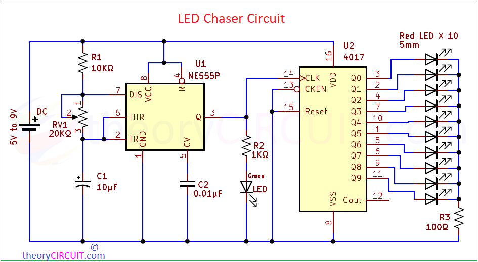
Circuit Diagram
Required Components
- Timer IC 555
- Decade Counter IC CD4017
- Red LED = 10
- Green LED = 1
- Resistor 10KΩ, 1KΩ, 100Ω each one
- Variable Resistor 20KΩ
- Capacitor 0.01μF
- Electrolytic Capacitor 10μF and 1μF
- DC power supply (5V to 9V)
- Connecting wires
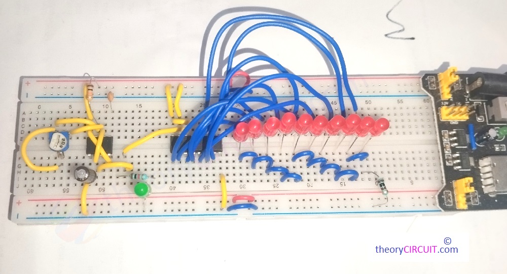
- breadboard or Dot PCB board
LED Light Chasing Video
Construction & Working
This circuit consists of two part one is Astable Multivibrator using Timer IC 555 to produce square pulse sequence and another one is Decade Counter using IC CD4017. LEDs are connected at the output ‘Q’ pins of 4017 IC. Here we used Red LED 5mm so that current consumption is very low hence we used only one 100Ω Resistor for protection. Green LED is used to indicate the pulse output from the timer IC.
IC CD4017 Counts Clock input and gives output at Q0 to Q9 pins, that is counts clock and gives 0 to 9 Ten outputs, One by one after each clock received at pin 14 (CLK). Here we using this to Glow LEDs and for Clock input We are using Astable multivibrator circuit.
As you can see in the circuit, Astable multivibrator formed by using IC 555 and timing components R1, RV1 (consider it as a R2 for calculation) and C1 and the output pulse frequency can be calculated as,
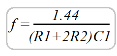
You can use Astable Multivibrator Calculator.
By changing RV1 value we can change the output square pulse frequency from IC 555 and so the Counting speed of CD4017 also gets change and makes each LED ON and OFF one by one. Here we used 10 LEDs so we used all Q outputs from Q0 to Q9, if you are using four, five or less than ten LEDs then connect next Q output pin to Reset pin. For an example if you are using Six LEDs and connecting it to Q0, Q1, Q2, Q3, Q4, Q5 and then connect next Q6 pin to Reset pin. Now the count resets after counting six from clock source.