Last Updated on March 24, 2024
An Important Electronic Circuit Since Vacuum Tube era is Audio Amplifier circuit. After the invention of transistors, and fast response Integrated Circuits Audio Amplifiers getting smart every week. To design robust audio amplifier we need to understand the basic things and basic operation of such amplifier. This article helps you to make an experiment for Audio Amplifier circuit using LM358.
We know that audio amplifier circuits are designed to increase the amplitude that is volume of audio signals., It takes a weak audio electric signal from an audio source (Mic or media player) and boosts it to a level that can drive speakers or headphones with sufficient power to produce audible sound.
As we know Audio amplifier have wide range of applications, depends on the signal source, purpose and output power, different types of amplifier can be build, like Class A, Class B, Class AB, Class D and Integrated amplifier. The following circuit can be used as direct audio amplifier or pre-amplifier for power audio amplifiers.
Circuit Diagram
Components List
- Operational Amplifier IC LM358 = 1
- Condenser Mic = 1
- Loud speaker 8Ω = 1
- Variable Resistor 100KΩ = 1
- Resistor 10KΩ = 3
- Resistor 680Ω = 1
- Electrolytic Capacitor 1μF, 10μF each one
Video
Construction & Working
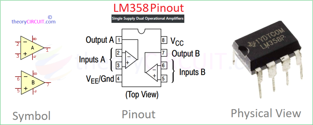
Single supply dual operational Amplifier IC LM358 is used in this circuit, when the amplifier needs high gain output then we can use both A & B internal operational amplifiers, for low power audio amplification and audio pre amplification single op-amp is enough. This IC can operate with minimum supply voltage from 3.0 V to maximum 32 V single rail supply. Refer Datasheet for more information.
LM358 Pinout
Condenser Microphone
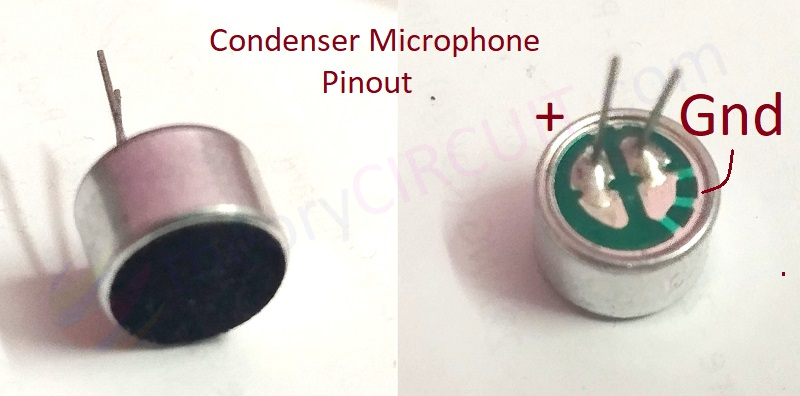
These condenser microphones are easily available few bucks component but best suitable device for converting voice into Audio electric signal. It is also being called as Capacitor Microphone because of its operation.
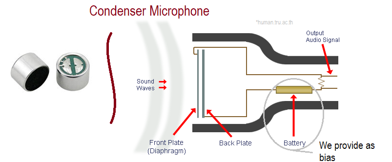
It consist of a thin front plate (thin diaphragm) close to a solid back plate and this setup creates capacitance between two plates. Whenever sound waves falls on thin front plate, it vibrates and makes changes in capacitance between two plates and it helps to convert equivalent audio electric signal.
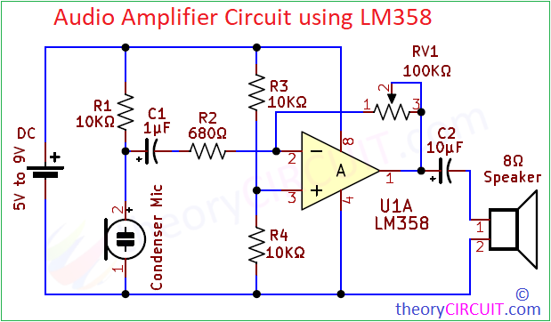
This Audio Amplifier uses single Op-Amp inside LM358 and configured in Inverting Amplifier with Negative feedback. A voltage divider is formed to bias Non-Inverting pin, for condenser microphone bias is applied through R1 Resistor and output signal is taken from the junction between R1 and cond. mic, Capacitor C1 is used to couple the audio signal to inverting pin through R2 Resistor. Amplified output signal is connected to the 8Ω loud speaker.
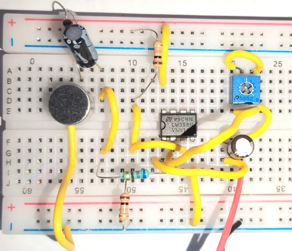
Prototype on Breadboard

Hello, I made the circuit and it works but its sound is not strong enough. What can I do? …(Translated)