
Last Updated on March 16, 2024
Frequency to Voltage Converter Circuits are very useful in applications like Speed & RPM Measurement, Flow rate measurement, Position sensing, Proximity and Distance sensing and Frequency synthesis etc.., These F to V or FVC circuits converts input signal frequency level to the proportional Voltage level output. By this way we can process and control actuators depends on the varying input frequency. This Frequency To Voltage Converter Circuit using LM331 IC can be used as input signal frequency transducer to the Microcontroller or Embedded System.
This circuit takes sine wave or square pulse as input and most suitable for square pulse and PWM signals and it can effectively take 10KHz frequency and generates a voltage output. Main part of this circuit is IC LM331 Precision Voltage to Frequency Converters / Frequency to Voltage Converters from Texas Instruments.
IC LM331
IC LM331 Family of Voltage to Frequency and Frequency to Voltage converters are ideally suited for use in simple low cost circuits and applications like, analog to digital conversion, precision frequency to voltage conversion, linear frequency modulation or demodulation, and many other functions. This IC can work in Single or split supply, as low as it can operate with 5V DC power supply. This IC consumes only 15mW during its operation with 5V DC bias. By implementing proper external components this IC can handle 1 Hz to 100 KHz frequency. It comes in PDIP (8) package.
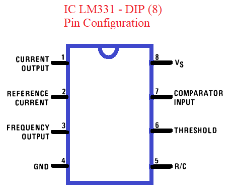
| Pin Number, Name | Pin Description |
| 1, IOUT | Current Output |
| 2, IREF | Reference Current |
| 3, FOUT | Frequency Output. This output is an open-collector output and requires a pullup resistor. (as per Datasheet claim) – <Here we used R1 to GND> |
| 4, GND | Power Supply Ground |
| 5, RC | R-C filter input (Resistor and Capacitor Filter Input) |
| 6, THRESH | Threshold Input Pin |
| 7, COMPIN | Comparator Input Pin |
| 8, VS | Supply Voltage Pin (Positive) |
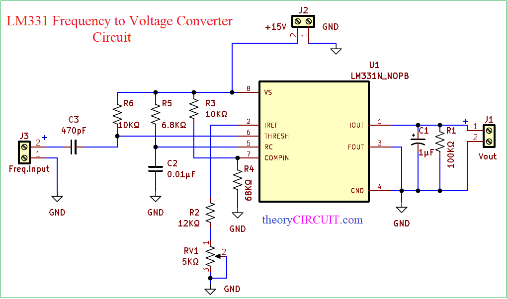
Circuit Diagram
Components Required (BOM)
| 1 | C1 | 1μF | CP_Radial_D4.0mm_P2.00mm | 1 | ||
| 2 | C2 | 0.01μF | C_Disc_D3.0mm_W1.6mm_P2.50mm | 1 | ||
| 3 | C3 | 470pF | C_Disc_D3.0mm_W1.6mm_P2.50mm | 1 | ||
| 4 | R3, R6 | 10KΩ | R_Axial_DIN0207_L6.3mm_D2.5mm_P10.16mm_Horizontal | 2 | ||
| 5 | R1 | 100KΩ | R_Axial_DIN0207_L6.3mm_D2.5mm_P10.16mm_Horizontal | 1 | ||
| 6 | R2 | 12KΩ | R_Axial_DIN0207_L6.3mm_D2.5mm_P10.16mm_Horizontal | 1 | ||
| 7 | R4 | 68KΩ | R_Axial_DIN0207_L6.3mm_D2.5mm_P10.16mm_Horizontal | 1 | ||
| 8 | R5 | 6.8KΩ | R_Axial_DIN0207_L6.3mm_D2.5mm_P10.16mm_Horizontal | 1 | ||
| 9 | U1 | LM331 | DIP-8_W7.62mm_LongPads | 1 | ||
| 10 | RV1 | 5KΩ | Potentiometer_Alps_RK09K_Single_Horizontal | 1 | ||
| 11 | J1 | Vout | TerminalBlock_bornier-2_P5.08mm | 1 | ||
| 12 | J2 | +15V | TerminalBlock_bornier-2_P5.08mm | 1 | ||
| 13 | J3 | Freq.Input | TerminalBlock_bornier-2_P5.08mm | 1 |
Construction & Working
We need only Resistors and Capacitors as external elements to construct fullscale working Frquency to Voltage Converter, A pulse input at Fin is Differentiated by a Capacitor and Resistor Network and the Negative going edge at Threshold Input Pin (pin 6) causes the input comparator to trigger the timer circuit. The average current flowing out of the Current Output Pin (pin 1) can be calculated as
Iaverage = i*(1.1*Rt*Ct)*f
As per our Designed circuit it should be re written as,
Iaverage = i*(1.1*R5*C2)*f
this current is filtered in the network RL = 100 kΩ and 1 μF. The ripple will be less than 10-mV peak, but the response will be slow, with a 0.1 second time constant, and settling of 0.7 second to 0.1% accuracy. Final Vout can be calculated as
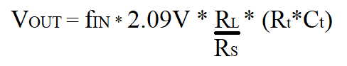
As per our Designed circuit it should be re written as,
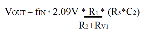
Here Iref input pin have Fixed Resistor R2 and Variable Resistor Rv1, Sum of these two resistors considered as Rs value.
Printed Circuit Board
LM331 Frequency to Voltage Converter Circuit PCB Gerber Files.
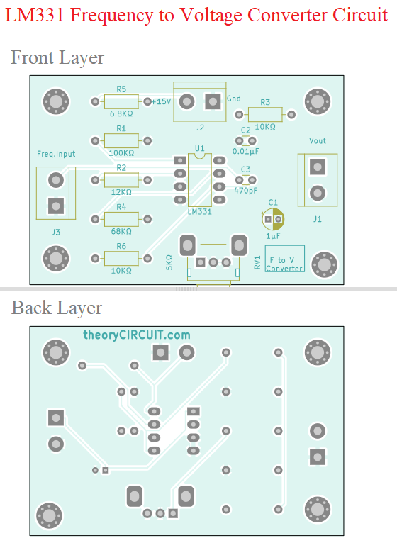
Interactive Board Viewer


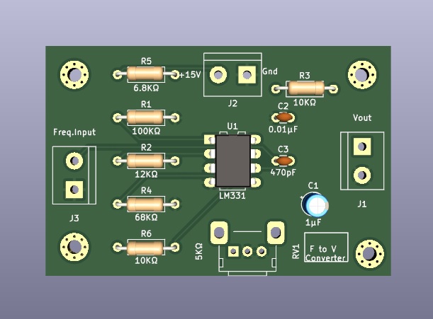
PCB 3D View
Further
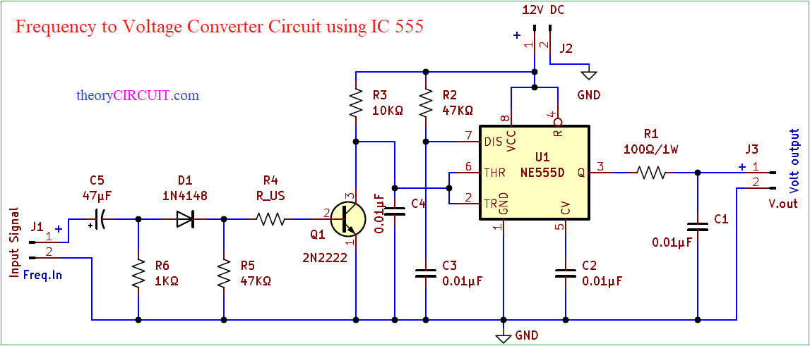
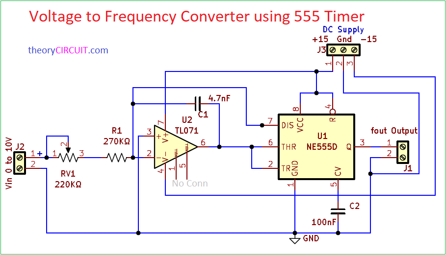
These FVC and VFC circuits are designed by using Timer IC 555.
This circuit can only be used for a frequency to voltage conversion of maximum input frequency of 10kHz,but in our circuit we want for some more kHz of maximum input frequency that can be converted,what can we do for that to increase the operating frequency range of this F to V converter?
Hi,
stay ≤ ~100 kHz for acceptable linearity and for best accuracy with low ripple stay below ~50 kHz if possible. At higher frequencies performance gets decline.
Here is the example components value for 50 KHz frequency input.
1. Rt = 6.8 kΩ (pin for timing) -> In our circuit R5 Resistor
2. Ct = 10 nF (NPO or C0G if possible) -> In our circuit C2 Capacitor
3. Rs = 12 kΩ (use 12k + 5k trimmer in series as mentioned in datasheet if you want trimming) -> In our circuit R2,RV1 Resistors
4. RL = 8.2 kΩ -> In our circuit R1 Resistor
5. Cfilter = 2.2 µF (prefer low leakage, low ESR and electrolytic for best stability output) -> In our circuit C1 Capacitor.
Remember to have common GND between Frequency source if it is external.