
Last Updated on May 5, 2024
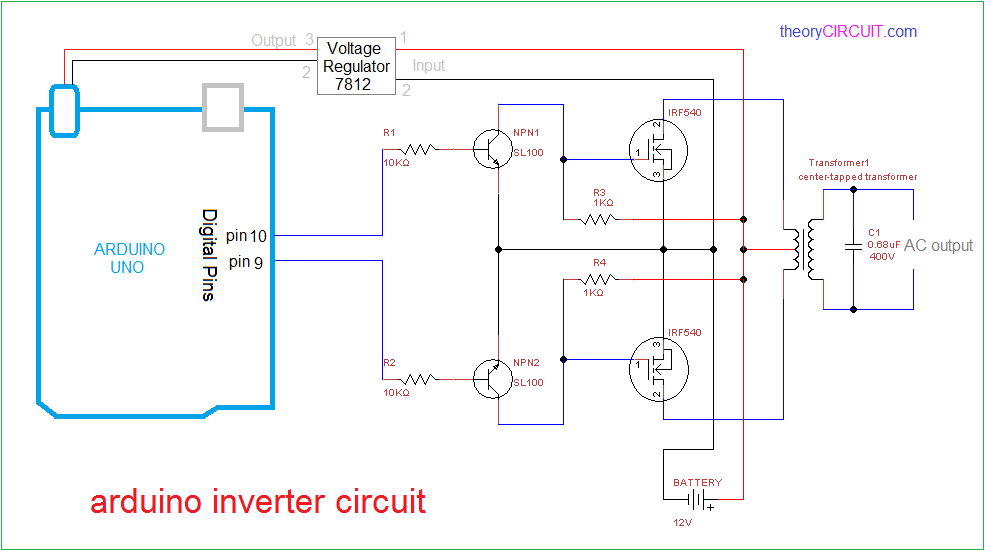
Inverter circuits are very helpful to produce AC supply when we need and it uses minimum level of DC bias from battery source. This Arduino Inverter Circuit can be used to convert 12V DC supply into 220V AC or 230V AC, by decreasing switching frequency we can obtain different level of AC output from inverted step down transformer.
Here the simple and reliable inverter circuit designed with Arduino board, and we can program Arduino to obtain stepped AC output, modified sinewave AC output or Pure sinewave output, and also we can program Arduino board to bring different range of frequency output.
Circuit Diagram
Construction & Working
This inverter circuit have three stages and a 12V 5.0Ah SLA battery as a DC bias, to show this circuit simple and neat I have removed battery charger circuit.
The first stage of this circuit is Arduino Micro controller board and it is programmed to give SPWM (Sinusoidal Pulse Width Modulation) or you can modify the code to produce different output from Arduino pins.
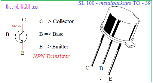
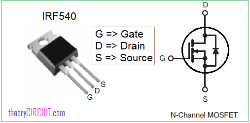
Second stage is switching and driver stage, output pulse from the Arduinio digital pins are fed into switching transistor SL100 npn and then power mosfet IRF540.
Third stage is a output stage which is constructed by using center tapped transformer (230 VAC primary / 12-0-12 VAC secondary) and it is connected reversely with driver circuit that is secondary stage (12-0-12 VAC) is connected to the power mosfet and primary side of transformer let to give output supply.
When the battery connected with this circuit voltage regulator 7812 powers up the Arduino board and it starts producing output pulses depends on sketch, the pulses are drives the transistor SL100 and power mosfet IRF540 and transformer secondary winding connected with the mosfet get discrete energy and mutually induce the large number of primary winding, as we know due to large numbers of winding and changing magnetic field, it produce high voltage AC output.
Arduino Inverter Code
This code to produce SPWM at pin D9 and D10 of arduino uno board, you can modify and comment your better arduino code.
const int SpwmArry[] = {500,500,750,500,1250,500,2000,500,1250,500,750,500,500}; // Array of SPWM values.
const int SpwmArryValues = 13; //Put length of an Array depends on SpwmArray numbers.
// Declare the output pins and choose PWM pins only
const int sPWMpin1 = 10;
const int sPWMpin2 = 9;
// enabling bool status of Spwm pins
bool sPWMpin1Status = true;
bool sPWMpin2Status = true;

void setup()
{
 pinMode(sPWMpin1, OUTPUT);
 pinMode(sPWMpin2, OUTPUT);
}

void loop()
{
 // Loop for Spwm pin 1
 for(int i(0); i != SpwmArryValues; i++)
 {
  if(sPWMpin1Status)
  {
   digitalWrite(sPWMpin1, HIGH);
   delayMicroseconds(SpwmArry[i]);
   sPWMpin1Status = false;
  }
  else
  {
   digitalWrite(sPWMpin1, LOW);
   delayMicroseconds(SpwmArry[i]);
   sPWMpin1Status = true;
  }
 }

 // Loop for Spwm pin 2
 for(int i(0); i != SpwmArryValues; i++)
 {
  if(sPWMpin2Status)
  {
   digitalWrite(sPWMpin2, HIGH);
   delayMicroseconds(SpwmArry[i]);
   sPWMpin2Status = false;
  }
  else
  {
   digitalWrite(sPWMpin2, LOW);
   delayMicroseconds(SpwmArry[i]);
   sPWMpin2Status = true;
  }
 }
}
Reference
NOTE:-
High Voltage and Current output Circuit. Handle with Care and Safety measures.
Similar Arduino Inverter Circuit

Since the code is using PD9 and DP10 ,is it possible to add a charge controller code that use different unused pins , please help , I have a code
Does it work properly
Thank you for sharing this design. Could you please advise the capacitor size.
Thanks for the details
if we use 3ah battery then what will happen.please explain.
please has anyone tested the above code if it worked properly?
Why are we taking the same output from two different pins?
because it feeds to two different side of the wave. If he had used one pin then both transistors would be activated at once..
Would it be possible to remove the transistors and just use logic level Mosfets instead?
why do we use 4 mosfets in inverter when it can work with 2 also as you have done
I guess it is because the circuit you are referring to is 24V DC input. But in this case the author has used 12V DC.
Also from your diagram 2 voltage of same magnitude and same sign are coming at the same time to the load make the voltage difference zero and no current will flow through the load
Big danger with that schema : when the DC power is applied, the arduino is not already booted, so the two sl100 are blocked, and the gates receive the +12 through R3 & R4, so all mosfet are blown.
To avoid that, I use a little relay 2 inverters driven by the arduino AFTER reboot, and connect R3 & R4 to the +12 THROUGH that relay.
jb
please share the cicuit which you design to resolve that issue..
it does not working
Excuse me Iam using 12v 7ah battery it will spark in breadboard then output load blink otherwise not maintaining it’s state continuously what happened please say me
hi.
I already have 400 V DC from solar panels so the transformer does no make much sense. how can I have ac sin wave without it?
please explain this code:
const int SpwmArry[] = { 193, 556, 851, 1044, 1110, 1044, 851, 556, 193}; // Array of SPWM values.
const int SpwmArryValues = 9; //Put length of an Array depends on SpwmArray numbers.
float Ts=0.02*1e6/18;
float M;
float outputValue;
// Declare the output pins and choose PWM pins only
const int sPWMpin1 = 10;
const int sPWMpin2 = 9;
const int AnalogInput = A0;
const int AnalogOutput = 11;
// enabling bool status of Spwm pins
bool sPWMpin1Status = true;
bool sPWMpin2Status = true;
void setup()
{
pinMode(sPWMpin1, OUTPUT);
pinMode(sPWMpin2, OUTPUT);
pinMode(AnalogInput, INPUT);
pinMode(AnalogOutput, OUTPUT);
}
void loop()
{
outputValue = analogRead(AnalogInput);
M = map(outputValue, 0, 1023, 0, 255);
analogWrite(AnalogOutput, M);
M=M/255;
// Loop for Spwm pin 1
for(int i(0); i != SpwmArryValues; i++)
{
digitalWrite(sPWMpin1, LOW);
delayMicroseconds((Ts- M*SpwmArry[i])/2);
sPWMpin1Status = true;
digitalWrite(sPWMpin1, HIGH);
delayMicroseconds(M*SpwmArry[i]);
sPWMpin1Status = !true;
digitalWrite(sPWMpin1, LOW);
delayMicroseconds((Ts- M*SpwmArry[i])/2);
sPWMpin1Status = true;
}
// Loop for Spwm pin 2
for(int i(0); i != SpwmArryValues; i++)
{
digitalWrite(sPWMpin2, LOW);
delayMicroseconds((Ts- M*SpwmArry[i])/2);
sPWMpin2Status = true;
digitalWrite(sPWMpin2, HIGH);
delayMicroseconds(M*SpwmArry[i]);
sPWMpin2Status = !true;
digitalWrite(sPWMpin2, LOW);
delayMicroseconds((Ts- M*SpwmArry[i])/2);
sPWMpin2Status = true;
}
}
Excellent data, very much useful