Last Updated on March 16, 2024
Detecting light or darkness brings lot of useful application hence Dark detector circuits using different light sensors are designed in this article. All dark detector circuits are implemented with few easily available components and each circuits are designed to give alert sound by buzzer, you can use your own application output actuator or microcontroller.
Based on the sensor and bias to the sensor, output and sensitivity may vary, so you should calibrate before implementing the circuit into application field.
Dark detector circuit using LDR
We know LDR be termed as Light Dependent Resistor or photo Resistor, this component Resistor value varies depends on the light intensity.
LDR Symbol
 LDR – Light Dependent Resistor
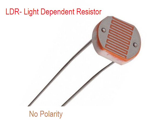
This LDR element will have two terminals and have one semitransparent CdS (Cadmium Sulfide) layer and impurity semiconductor makes this device photosensitive depends on the light intensity, Resistance of this device will vary depends on light, this character is used in many light related applications.
Circuit diagram
Construction & Working
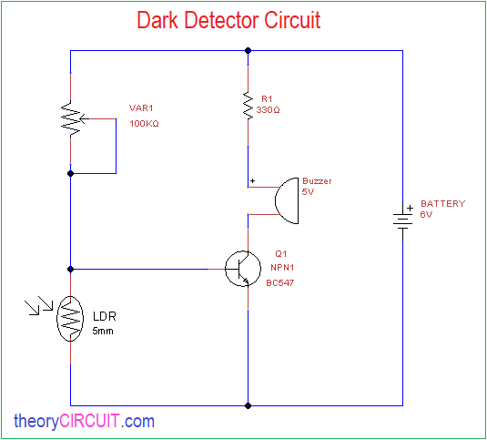
Small size LDR connected to the power supply through variable Resistor VR1 and by varying this we can change the sensitivity level and then transistor Q1 base connected to the LDR pin and buzzer is connected through transistor collector terminal. When the light falls on the LDR it becomes less Resistive and the transistor base don’t get supply and becomes in cutoff stage, when the LDR sense dark then it become as high resistance element and positive supply through variable resistor reaches the transistor base and transistor gets turn ON and buzzer starts produce beep sound.
Dark detector circuit using Photodiode
photodiode is a active light detecting element and it controls the current flow this element depends on the light intensity.
Photodiode Symbol

Photodiode
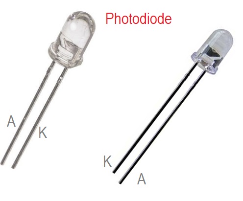
photodiodes are available in different parameters, we can choose depends on our expectations, this photodiode has p type semiconductor and N type semiconductor separated by the Intrinsic layer and this layer release electrons when receives photons.
Circuit Diagram
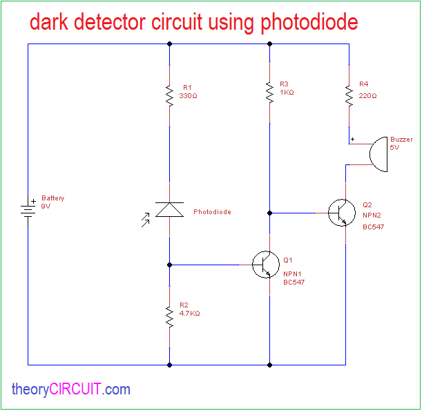
this circuit produce beep sound through buzzer if the photodiode exposed to the darkness. Sensitivity of this photodiode can be varied through R1 & R2 Resistors.
Dark detector circuit using Phototransistor
phototransistor is a active photo sensitive device and it control the current flow depends on the light intensity.
Symbol of phototransistor
![]()
Phototransistor
![]()
The phototransistor will have N,P,N or P,N,P semiconductor layers separated by i Intrinsic or photosensitive semiconductor.
Circuit Diagram
![]()
This circuit will provide beep buzzer sound when the phototransistor exposed to the darkness the sensitivity of this circuit can be varied by changing R1 and R2 Resistor Values.