Last Updated on March 16, 2024
We can create Emergency Fan Circuit which will helps in multiple tasks by using 9V DC fan. The following prototype is very simple and easy to construct, It has only few elements, It acts as a Battery charger circuit and DC fan circuit.
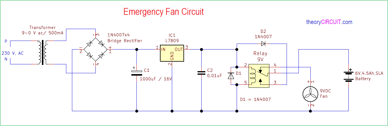
This circuit contains Bridge rectifier, Voltage Regulator and Relay Fan switch stages. Here 230V AC to 9V AC step down transformer used and Bridge Rectifier module is used you can construct rectifier using four 1N4007 diode also.
Circuit Diagram
Components Required
- Step down transformer 9-0 V AC
- Bridge Rectifier module (or) 1N4007 = 4
- IC 7809
- Relay 9V
- Diode 1N4007 = 2
- Capacitor 1000μF/16V, 0.01μF each one
- 9V DC Fan
- 6V, 4.5Ah SLA Battery
Construction & Working
Emergency fan circuit is a multipurpose circuit, you can built this circuit starting with step down transformer and bridge Rectifier, Regulate output DC with IC7809 and then DC supply is directed to Relay coil and N/O (Normally Open contact) of Relay, the common terminal of Relay is connected with SLA battery positive terminal, N/C (Normally Close) terminal is connected with DC Fan.
When the supply is present the Relay coil gets energized and attracts common terminal lever to N/O contact and makes the SLA battery charging. If the power failure occurs the Relay coil de-energized and common terminal makes contact with N/C contact and hence DC Fan starts to rotate.