Last Updated on October 11, 2024
Here is the simple method to Interface Photoresistor with ESP32 board. A Photoresistor also known as LDR (Light Dependent Resistor) changes its Resistance value between their terminals depends on the light intensity falls on its sensing surface. By using this characteristic we can build tons of useful applications starting from Automatic street light control to Home Automation, Solar tracking etc.,
Here we going to interface LDR with ESP32 and read its value through Serial monitor in Arduino IDE. If you are new to ESP32 and Arduino IDE then read here to get started.
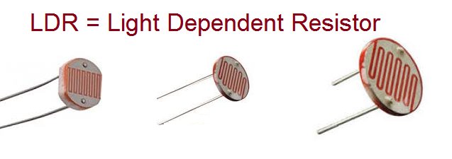
What is LDR (or) Photoresistor?
LDR (or) Photoresistor is an electronic component with two terminals and available in different size sensing area like 3mm, 5mm, 10mm etc., the sensing area is made of Semiconductor materials called Cadmium Sulfide (Cds), free electrons in the outer band jumps to conduction band, when the light falls on the Cds material. So this material gives different level resistance to flow of electrons depends on the light falls on it.
LDR (or) Photoresistor build with Cds will have the following Characteristics.
- High Resistance in Darkness. In low light or darkness this device will give high Resistance to flow of Current/Voltage in the range of Megaohms.
- Low Resistance in Bright Light. Under bright light condition this LDR Resistance can drop to few hundred ohms.
- By using it in a Voltage Divider setup we can adjust its Sensitivity.
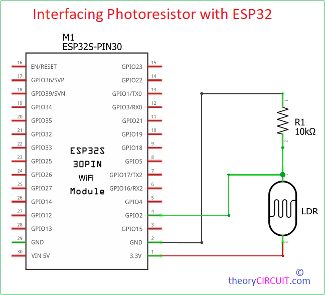
Circuit Diagram
Components Required
- ESP32 board
- LDR (Photoresistor)
- 10KΩ Resistor (for voltage divider)
- Breadboard and Jumper Wires
- USB Cable (to program the ESP32)
- Computer with Arduino IDE
Construction & Working
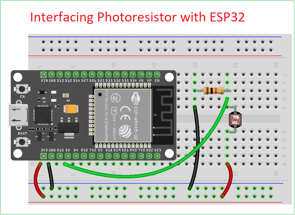
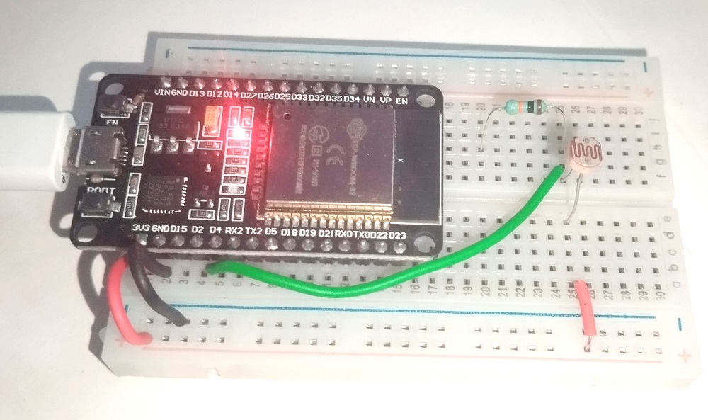
To read the LDR (or) Photoresistor value, we have to connect it through Voltage divider configurations, which will convert the changing Resistance of the LDR into a changing voltage that can be read by the ESP32 board or any other microcontrollers.
Connect positive supply 3.3V to a terminal of LDR and then connect another terminal to Resistor 10KΩ, then connect 10KΩ Resistor another terminal to Gnd. This two will form a voltage divider setup. Now take output from the junction point between LDR and Resistor. Connect the output to GPIO 2 of ESP32 board (you can use any one ADC enabled GPIO pin).
To read the output analog values from the LDR, we need to use internal ADC of ESP32, it have several ADC channels that can read analog voltage and convert it into a digital value ranging from 0 to 4095, based on the resolution (12-bit by default). Here we used GPIO 2 (ADC2_2), so that we have to mention it on the Arduino Code.
Arduino Code to Read LDR (or) Photoresistor
// Define the LDR pin
const int LDR_PIN = 2; // Use GPIO 2 for analog input

void setup() {
  // Initialize Serial communication
  Serial.begin(115200);

  // Setup the analog pin (no need for pinMode as analog pins are input by default)
}

void loop() {
  // Read the analog value from the LDR (0 to 4095)
  int ldrValue = analogRead(LDR_PIN);

  // Convert to voltage (ESP32 has a 3.3V ADC reference)
  float voltage = ldrValue * (3.3 / 4095.0);

  // Print out the raw value and voltage
  Serial.print("LDR Value: ");
  Serial.print(ldrValue);
  Serial.print(" | Voltage: ");
  Serial.println(voltage);

  // Add a small delay for stability
  delay(500);
}
Video