Last Updated on April 20, 2024
As we know many electronic circuits and microcontrollers require a source of signal with specific frequency and amplitude, which may range from few Hz to Several GHz. To provide this type of signal we use circuit called Oscillator. Here simple Hartley Oscillator circuit designed to provide wide range of sinusoidal output.
Every sinusoidal Oscillator circuit will have Tank circuit, Amplifier circuit and feedback path, here the feedback should be positive and the oscillator circuit must obtain undamped output. This Hartley oscillator Circuit widely used in radio communication and audio system.
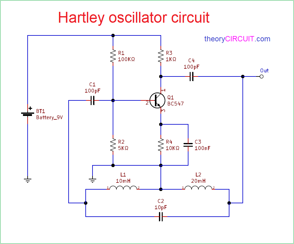
Hartley oscillator Circuit Diagram
Components Required
- Battery 9V
- Transistor BC547
- Inductor 10mH, 20mH each one
- Capacitor 10pF, 100nF each one
- Capacitor 100pF = 2
- Resistor 100KΩ, 5KΩ, 1KΩ, 10KΩ
Circuit Construction & Operation
Hartley Oscillator circuit has tank circuit with two Inductors and one Capacitor, here BC547 transistor acts as single transistor amplifier in common emitter configuration. Output is taken from the Collector terminal of BC547 transistor through output coupling capacitor C4. Feedback path is connected between collector and base through tank circuit.
When we apply power supply to this circuit collector current starts rising and charges the capacitor C in the tank circuit. When the Capacitor gets full charge then it discharge through L1 and L2 inductors and it starts the initial oscillation. Hence the induced oscillation across the L1 is applied between Emitter and Base terminal of amplifier and this will get amplified and then applied again to the feedback (tank elements) here tank circuit produce 180º phase shift to the signal and Transistor amplifier creates 180º phase shift to the signal during amplification and hence total 360º phase shift is produced between the input and output signal of tank circuit.
Hartley Oscillator circuit formula
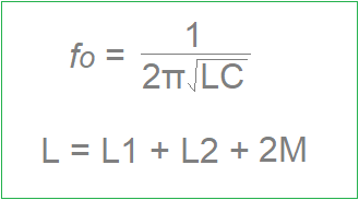
Where,
- C is Capacitor in tank circuit (C2)
- L is total value of Inductor L1 and L2 in tank circuit and 2M is mutual inductance (only use 2M if two coils L1, L2 are wound on same core).
This circuit is capable to produce sinewave signal frequency range from 20KHz to 90KHz.
The biasing for this circuit is wrong and possibly the feedback drive from the collector is a bit low. Change R2 to 50k and R3 to 10k and increase C4 and C1 to 100nF.
Please see my comments under the Colpitts circuit also.