Last Updated on March 29, 2024
Li-Po Battery or Lithium-ion Polymer battery is a Rechargeable battery which uses a polymer electrolyte instead of a liquid electrode. This battery can be termed as LiPo, Li-Poly, LIP, Lithium-Poly etc., This Lipo battery comes in different shape size and different voltage, current rating for an example.
1Cell lipo battery = 3.7V to 4.2V
3Cell lipo battery = 11.1V to 12.6V
6Cell lipo battery = 22.2V to 25V
By connecting more cell Lipo we can get higher voltage battery pack. LiPo battery can be dangerous when overcharged, undercharged or discharged at a faster rate than the safe rate. Hence we need right LiPo Battery charger circuit.
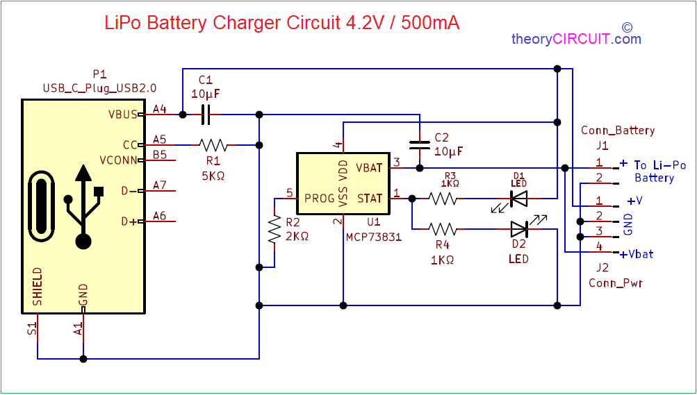
Circuit Diagram
Components Required (BOM)
| 1 | C1, C2 | 10µF | C_0805_2012Metric | 2 | ||
| 2 | R3, R4 | 1KΩ | R_0805_2012Metric | 2 | ||
| 3 | R1 | 5KΩ | R_0805_2012Metric | 1 | ||
| 4 | R2 | 2KΩ | R_0805_2012Metric | 1 | ||
| 5 | D1, D2 | LED | LED_0805_2012Metric | 2 | ||
| 6 | U1 | MCP73831 | SOT-23-5 | 1 | ||
| 7 | J1 | Conn_Battery | JST_EH_B2B-EH-A_1x02_P2.50mm_Vertical | 1 | ||
| 8 | J2 | Conn_Pwr | PinHeader_1x04_P2.00mm_Vertical | 1 | ||
| 9 | P1 | USB_C_Plug_USB2.0 | USB_C_Receptacle_GCT_USB4085 | 1 |
Construction & Working
Li-Po Battery charger circuit designed by using IC MCP73831. This IC MCP73831 from microchip is a miniature single cell, fully integrated li-ion, li-polymer battery charge management controller. This IC can be programmed to give 100 mA to 1000 mA charging current. This IC comes in 8-lead DFN and 5 lead SOT-23 packages.
This Lipo battery charger circuit designed to charge 4.2V battery and gives 500mA charging current. Input for this circuit comes from USB C Receptacle GCT USB 4085. Hence we can easily connect and charge Lipo battery.
This circuit provides Pin header and JST battery connector, hence we can connect Lipo battery in these two way. In this circuit D1 LED indicates the charging status and D2 LED indicates the full charge condition or charge done.
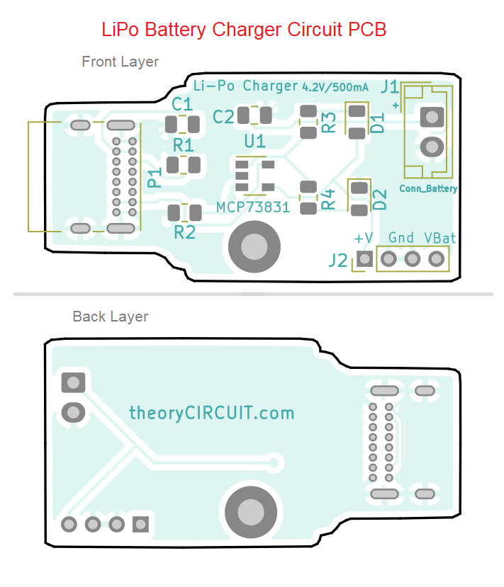
Printed Circuit Board
LiPo Battery Charger Circuit PCB Gerber Files.
Interactive Board Viewer


Hey there, theory circuit. Was curious if you could tell me if the B5, A7 and A6 pins from the USB C socket are doing anything in the actual final PCB project, cause they seem to just be hanging without a No_Conn or something similar.
I’m confused whether they actually have a use or they’re just left there in the symbol without a real purpose for this project?
Hi Cristi
Those are data lines (B5, A7 and A6) for lipo battery charger circuit we only need DC supply and we get it from A4 and A1. So the terminals B5, A7 and A6 kept open purposely.
If I want to connect a load (at the moment just a small motor) to this that can be powered by either over the USB or the battery how would I go about doing so?
My assumption is that I connect the load to GND and VBAT to have it use the battery. But how would I go about connecting +V?
I am very new to all this so it might be obvious how to do this, but I am not so sure.
you would need a charging ic that can handle dynamic power path called load sharing. check Texas instruments IC bq2403x