
Last Updated on July 31, 2025
We mostly use Lithium Batteries for our electronic projects and applications. But these batteries are sensitive to overcharging and little high temperature, these conditions may lead to battery fire and explosion. Here is the simple Automatic Lithium Battery Charger Circuit suitable for Li-Ion batteries 3.7V to 4.2V and 18650 batteries. This circuit constructed by using LM358 dual operational amplifier, S8550 PNP transistor and Indicator LEDs. This charger circuit is designed to automatically change output voltage from charging to maintenance voltage, when the target battery fully charged and starts to overflow. By this way it avoids overcharging.
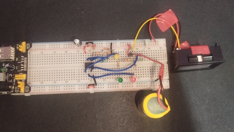
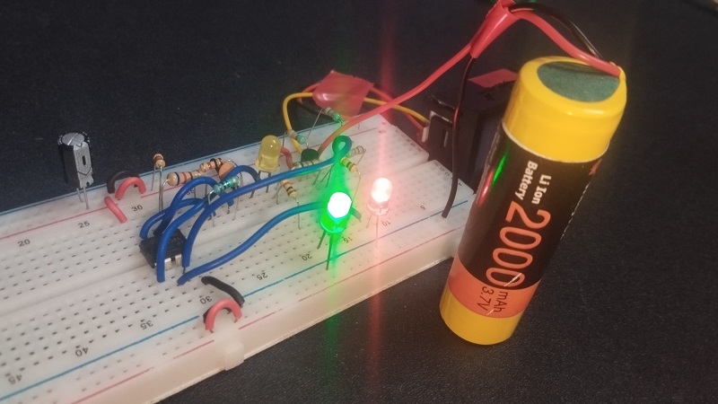
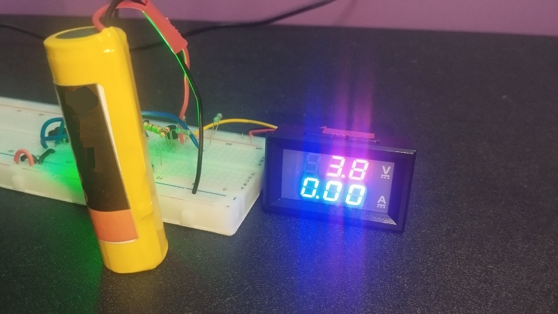
Here we have used 18650 Li-Ion battery 3.7V / 2000 mAh as a load and constructed this circuit on breadboard to test.
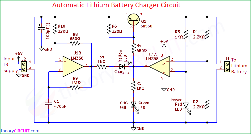
Circuit Diagram
Components Required
| 1 | C1 | 470pF | C_Disc_D3.8mm_W2.6mm_P2.50mm | 1 | ||
| 2 | C2 | 100μF | CP_Radial_D4.0mm_P2.00mm | 1 | ||
| 3 | R3, R5, R7 | 1KΩ | R_Axial_DIN0207_L6.3mm_D2.5mm_P10.16mm_Horizontal | 3 | ||
| 4 | R1, R2 | 2.2KΩ | R_Axial_DIN0207_L6.3mm_D2.5mm_P10.16mm_Horizontal | 2 | ||
| 5 | R4, R8 | 680Ω | R_Axial_DIN0207_L6.3mm_D2.5mm_P10.16mm_Horizontal | 2 | ||
| 6 | R6 | 220Ω | R_Axial_DIN0207_L6.3mm_D2.5mm_P10.16mm_Horizontal | 1 | ||
| 7 | R9 | 1MΩ | R_Axial_DIN0207_L6.3mm_D2.5mm_P10.16mm_Horizontal | 1 | ||
| 8 | R10 | 22KΩ | R_Axial_DIN0207_L6.3mm_D2.5mm_P10.16mm_Horizontal | 1 | ||
| 9 | U1 | LM358 | DIP-8_W7.62mm_LongPads | 1 | ||
| 10 | Green1, Red1, Yellow1 | LED | LED_D5.0mm | 3 | ||
| 11 | Q1 | S8550 | TO-92_Inline | 1 | ||
| 12 | J1, J2 | Screw_Terminal_01x02 | TerminalBlock_Altech_AK300-2_P5.00mm | 2 |
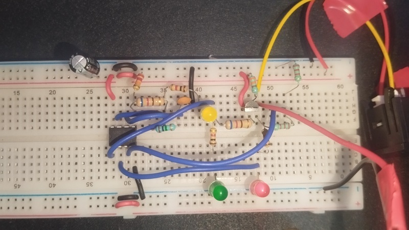
Prototype on Breadboard
Construction & Working
Main operation of this circuit is to detect the Battery Voltage, Control Charging Voltage and Indicate charging and full status using LEDs. Dual operational amplifier LM358 used as a comparator to perform all the operations. Transistor S8550 delivers controlled charge voltage and current to battery.
Input DC Power Supply 5V is applied through J2 connector. This is suitable for 3.7V with 4.2V full charge voltage Li-Ion batteries. Red LED connected through R3 indicates output power supply from the Q1 transistor. A Voltage divider made from R1 and R2 Resistors takes voltage from the battery and divided voltage is applied to the Non Inverting input pin 3 of op-amp U1A inside the LM358. U1A op-amp inverting input is taken between R3 and power indicator LED. This is slightly higher than divider voltage from R1,R2.
When the battery connected at J1 connector not fully charged, then its voltage through voltage divider at pin 3 is lower than the reference at pin 2. This difference makes the output of U1A LOW and makes Charging LED Glow and allows S8550 transistor in ON condition so that battery gets charge voltage/current.
When the battery gets fully charged then the voltage divider voltage becomes higher than inverting input. That is pin 3 voltage higher than pin 2 of U1A op-amp. So that this inverting voltage comparator gives HIGH output and makes CHG Full LED to glow and also makes S8550 PNP transistor OFF (below saturation). Hence there is minimum output voltage to battery, that is stopping battery charge. U1B op-amp makes Yellow LED (Charging) blink during charge cycles, using C1 as a timing capacitor.
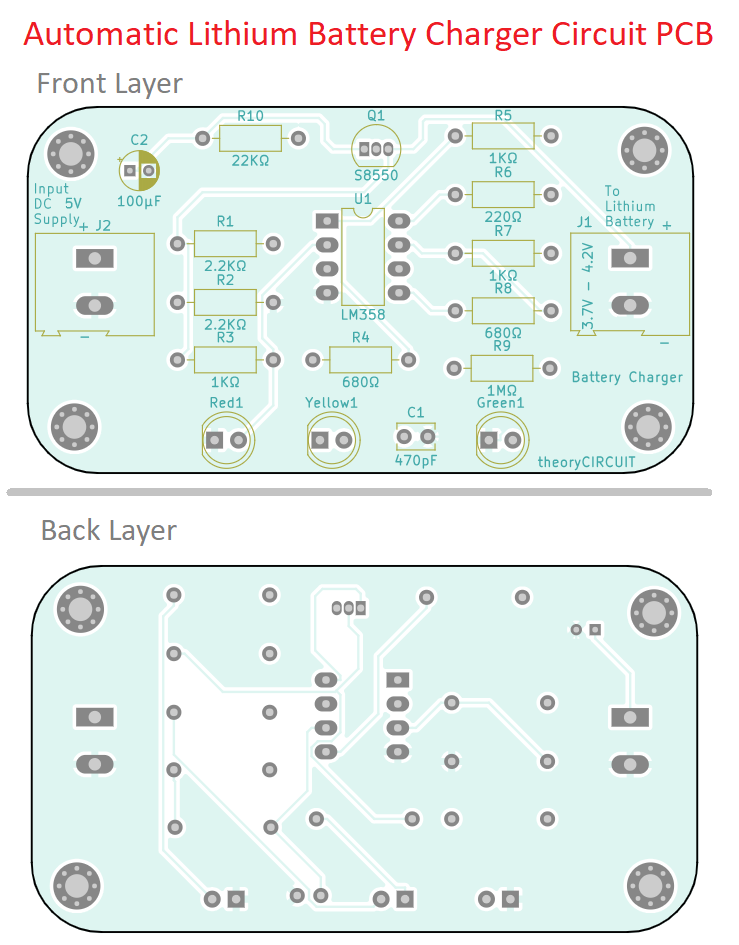
Printed Circuit Board
Automatic Lithium Battery Charger Circuit Gerber Files.
Interactive Board Viewer


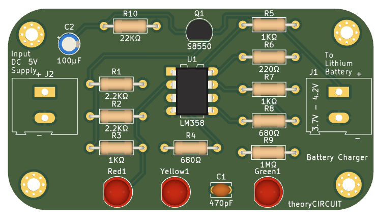
PCB 3D View
Is there anything to limit the charge current?
Not looks like this. Additionally, LiIon needs relatively precise 4.2V and 1:1 voltage divider compared vs just some red led makes quite crude voltage reference – so exact voltage battery would reach can be sizably different. Photo shows 3.8V but if LiIon reaches just 3.8V it hardly fully charged. Proper charging sequence is current limited charging to 4.2V (can be a bit more for some modern chemistries, like 4.3, 4.35 or even 4.4V) and then constant voltage as current decays. Though it it would stop at 3.8V it at least wouldn’t do dangerous overcharge.