
Last Updated on March 16, 2024
Emergency tube light circuits serve a critical role in providing illumination during power outages or emergencies. As an electronics and communication engineer with a passion for designing electronic circuits, you can appreciate the significance of these circuits. Primarily, they address the need for a reliable light source when the regular power supply fails unexpectedly. This ensures safety by preventing accidents and aiding in a swift and orderly evacuation, especially in areas like stairwells and hallways. Moreover, compliance with building codes and safety regulations often mandates the installation of emergency lighting systems. These circuits typically incorporate backup power sources like batteries, ensuring continuous operation even in the absence of the main power supply. From a security standpoint, emergency lighting enhances visibility during disruptions, crucial in public spaces and residential complexes. Not much.., here is the simple but effective Emergency Tube light circuit. 20 watts fluorescent emergency light is constructed with few simple components and 12 volt 7Ah battery.
Before LEDs and even now one of the reliable light source is Tube light, few lines about it before jumping into the circuit diagram, A fluorescent tube light is a gas discharge light that uses electricity to excite mercury vapor, generating ultraviolet light. This UV light interacts with a phosphorescent coating inside the tube, causing it to emit visible White light. This type of tube lights are Known for energy efficiency and longevity, fluorescent tube lamps have advantages over incandescent bulbs. However, they may have drawbacks like a brief warm up period and trace amounts of mercury.
Circuit diagram for Emergency Tube Light
This Circuit involves in Handling of High Voltage AC supply, Handle with extreme care, Handling high voltage AC supply requires extreme caution to prevent accidents and ensure personal safety.
Components List
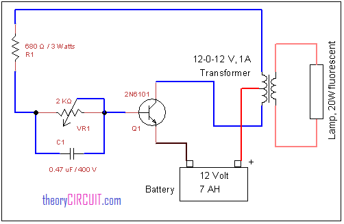
- 6″ 4W fluorescent lamp or 12″ 8W fluorescent lamp
- Center tap Step down transformer 230VAC to 12-0-12VAC / 1A
- 12 Volt 7AH Lead Acid battery
- Transistor 2N6101
- Variable Resistor 2KΩ
- Capacitor 0.47μF /400V
- Resistor 680Ω/3W
2N6101 Pinout

The 2N6101 is an NPN bipolar junction transistor (BJT) widely utilized in electronic circuits for amplification and switching applications. As an NPN transistor, it operates by allowing a small current to control a larger current flow from the collector to the emitter. The 2N6101 is available in various packages, including the commonly used TO-92 and TO-220. Its versatility makes it suitable for a range of electronic designs, where it can be employed to amplify signals or serve as a switch. With closed eyes we can appreciate its ability to efficiently control electronic currents and voltages, contributing to the overall functionality of electronic systems.
Construction and Working
In this circuit (12-0-12V) step down transformer is utilized as the fluorescent driver transformer that is the primary winding terminal is connected to the 20 watts fluorescent light and secondary (12-0-12V) center tapped terminals are connected with switching pulse circuit.
Here VR1 variable resistor and C1 capacitor is responsible for switching pulse that is applied to the switching power transistor Q1, 2N6101.(search in google to identify the pinout) This transistor connects and disconnects secondary winding of transformer with battery supply hence it produce EMF on winding this EMF increases in primary winding (step up) and the supply is enough to drive the 20 watts fluorescent light.