
Last Updated on June 9, 2024
Uninterrupted power supply is crucial, especially for electronic devices and systems. Power interruptions or failures can lead to several risks. To keep eye (ear) on the mains power supply all the time, here is the simple and easy to construct Mains Power Interruption or Failure Alarm Circuit design. This circuit produce long buzzer beep sound when there is power interruption or failure.
Power interruption can be happen any time due to Electrical grid issues, Natural disasters or maintenance activities. Regardless of the cause, being prepared about a power failure is essential. This power failure alarm circuit gives you notification and you can take necessary actions.
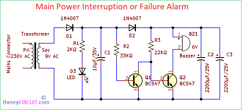
Circuit Diagram
Components Required
| 1 | C2, C3 | 2200μF/25V | CP_Radial_D10.0mm_P5.00mm | 2 | ||
| 2 | C1 | 10μF/35V | CP_Radial_D8.0mm_P3.80mm | 1 | ||
| 3 | R1 | 2KΩ | R_Axial_DIN0207_L6.3mm_D2.5mm_P10.16mm_Horizontal | 1 | ||
| 4 | R2 | 33KΩ | R_Axial_DIN0207_L6.3mm_D2.5mm_P10.16mm_Horizontal | 1 | ||
| 5 | R3 | 22KΩ | R_Axial_DIN0207_L6.3mm_D2.5mm_P10.16mm_Horizontal | 1 | ||
| 6 | D1, D2 | 1N4007 | D_DO-41_SOD81_P10.16mm_Horizontal | 2 | ||
| 7 | D3 | LED | LED_D5.0mm | 1 | ||
| 8 | Q1, Q2 | BC547 | TO-92L | 2 | ||
| 9 | BZ1 | Buzzer | Buzzer_15x7.5RM7.6 | 1 | ||
| 10 | J1 | 9V AC | TerminalBlock_Altech_AK300-2_P5.00mm (Stepdown Transformer) | 1 |
Working Video
Construction & Working
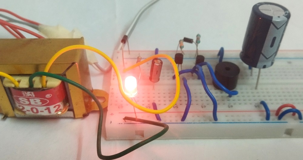
This circuit uses Capacitor stored energy to produce buzzer beep sound during mains power failure. Get 9V AC supply from the Mains power supply you want to monitor, here we have used 9V/500mA stepdown transformer. Then the AC supply rectified by the D1 diode and LED here indicates the presence of power supply. Transistors Q1 and Q2 configured as cascade switch. Capacitor C2 and C3 stores energy when the power supply presence. 6V Buzzer is connected to the collector terminal of Q2. Didoe D2 blocks charge of capacitor C2, C3 before reaching base of Q1 Transistor.
Consider there is a power supply, during this time Transistor Q1 gets bias through Resistor R2 hence gets turn ON and grounds supply coming out through R3, So the transistor Q2 don’t get base bias and stays in OFF condition, so there is no buzzer sound. When power interruption or failure occurs Q1 don’t get base bias but Q2 gets both base bias and also collector bias through capacitor C2, C3 (Discharging). and makes Buzzer beep sound. So that you know there is a power interruption occurs.
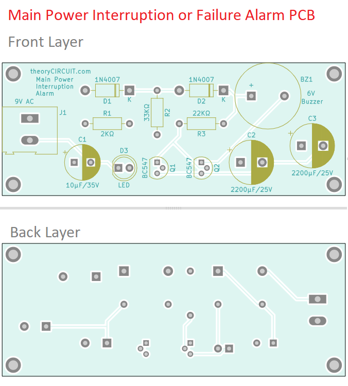
Printed Circuit Board
Main Power Interruption or Failure Alarm Circuit PCB Gerber Files.
Interactive Board Viewer


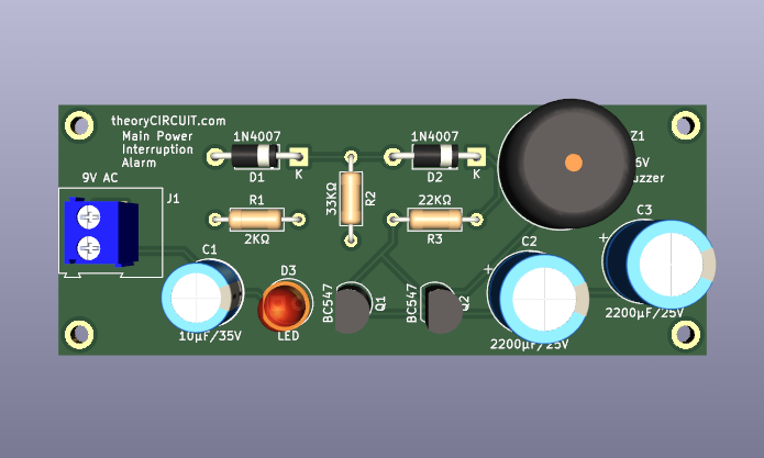
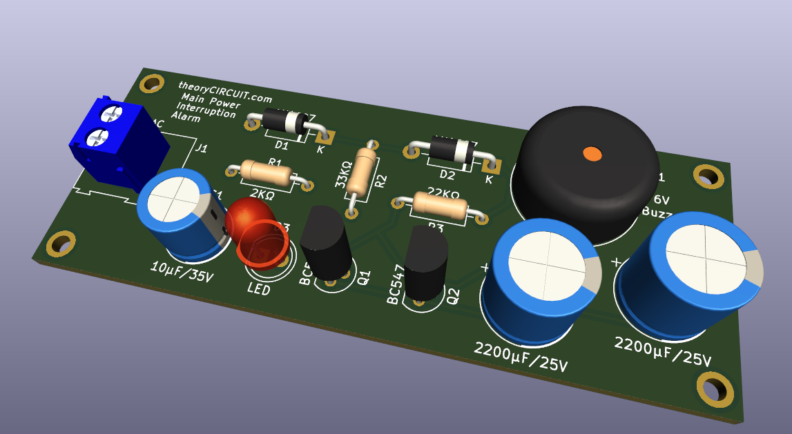
PCB 3D View
Breadboard prototype
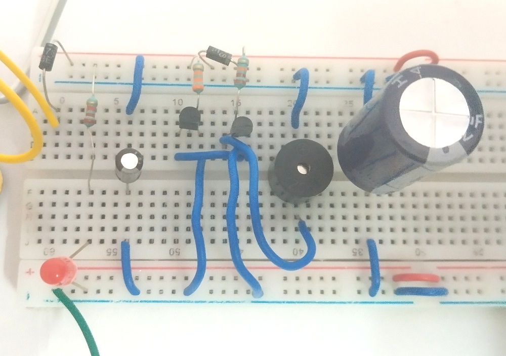
By adding 4700μF/25V (C2) Capacitor we can increase the time of buzzer sound.