Last Updated on March 16, 2024
This LDR switch relay circuit eliminates the physical contact with electrical appliance switch, consider the bath room switch, if we use our wet finger to turn on or off it may give electric shock sometimes it would be dangerous to avoid this situations we can use this simple LDR switch relay circuit.
Here LDR acts as shadow sensing devices and makes turn ON or OFF the Relay when ever it detects the shadow and keep the relay in either ON or OFF condition until the next detection of shadow. Here we can swipe our hands above the LDR to turn ON/OFF the electrical appliances.
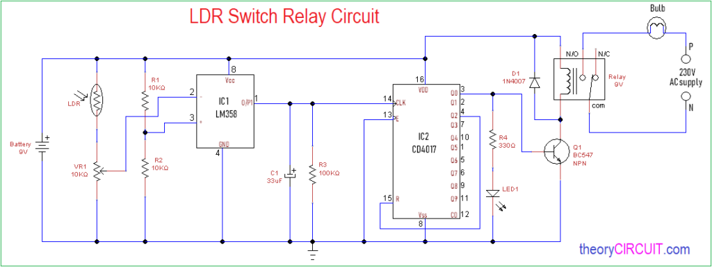
Circuit Diagram
Components Required
- Decade Counter IC CD4017
- Dual operational amplifier IC LM358
- 9V Relay module
- LDR (Light Dependent Resistor)
- Variable Resistor 10KΩ
- Resistor 10KΩ-2
- Resistor 100KΩ
- Resistor 330Ω
- Capacitor 33uF / 16V
- Diode 1N4007
- LED green
- Transistor BC547
- Battery 9V or (Use 9V DC power supply)
- 230V AC bulb
Construction & Working
This LDR switch relay circuit has two sections one is sensor-operational amplifier and another one is decade counter to drive the Relay. LDR is connected with Variable resistor VR1 and variable terminal connected with operational amplifier inverting input by changing the value of VR1 we adjust the sensitivity level of LDR. The non inverting input of operation amplifier LM358 is balanced with Voltage divider R1 and R2 resistors. Output of operational amplifier one is obtained from pin 1 and fed into clock input of Decade counter. Here C1 and R3 stabilize the output from operational amplifier.
The IC CD4017 counts the clock and gives 10 output from Q0 to Q9, here output relay connected with Q0 through switching transistor BC547 and a LED1 indicates the ON condition of relay. Electrical appliance (bulb) is connected between N/O (Normally Open) and Common pin. When the LDR detects the Shadow then Relay gets supply and turns ON the bulb and stays in same condition until another shadow detection by the LDR.
Reference:-
If your using this circuit as permanent setup then you can use Step down transformer and rectifier-regulator to have 9V DC power supply.


Do we need dedicated light source?
is it work in dark condition?