Last Updated on March 16, 2024
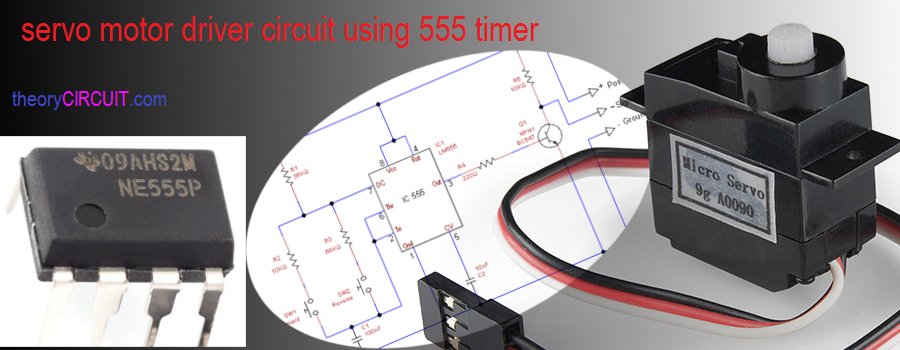
Servo motors are made for precise control of angular or linear position, Velocity and acceleration. These servo motors are called as Rotary actuator or linear actuator. Servos may contain sensor for position feed back and signal input for position control. Servo motors are available in different size and voltage ratings. All servo motors are works in the same way but depends on the size and specifications output volume varies.
Here sub micro size servo motor is taken as a target device and we developed servo motor driver circuit for that motor. Servo motors are widely used in different types of applications and suitable for movement or rotation based mechatronic needs.
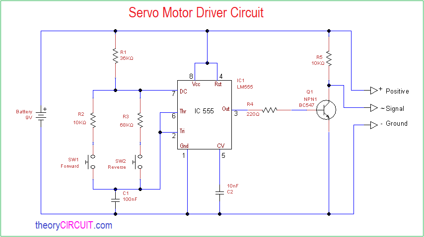
Circuit Diagram
Construction & working
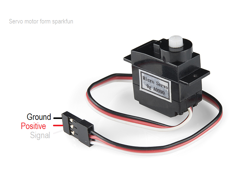
Every servo motors will have three terminals, one for positive supply, another for ground supply and other one for position control signal input.
This circuit is designed to give PWM (Pulse Width Modulation) signal output by using this different duty cycle PWM pulse, we can control the servo motor rotation and position.
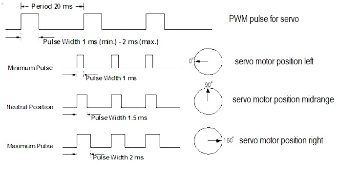
This illustration given to understand the servo rotation based on PWM signal. Consider the signal with 20ms period and width of HIGH pulse duration 1ms (min) and 2ms (max), depends on the HIGH pulse signal time duration servo motor rotation gets change.
Here the timer IC 555 employed as a astable multivibrator and it produce pulse at output with two different pulse duration, we know the output pulse time in 555 is depends on the timing Resistor and timing Capacitor.
High pulse time TH = 0.693*(RA + RB)*C
Low pulse time TL = 0.693*RB*C
NOTE:- Here RA is R1 Resistor and RB is either R2 or R3 depends on the button (SW) pressed, its for this circuit only.
When the switch SW1 close, the 555 timer IC produce long duration High pulse and servo rotates in right direction. When the switch SW2 close, the 555 timer IC produce short duration High pulse and servo rotates in left direction.
Note:- Depends on the output pulse duty cycle, servo motor rotation direction and speed gets change.
Where do I connect the three(positive, negative and ground signal) output terminals?
Those are the three connections to the Servo…..Duh!!!!!
What is the purpose of the transistor????