
Last Updated on March 16, 2024
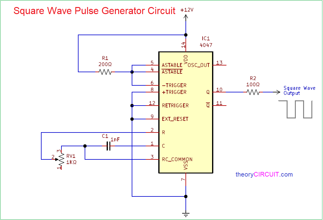
Digital circuits and logic circuits will need external square pulse as a clock signal or carrier signal. We don’t need complex circuit to produce square pulse signal, here simple Square Wave Pulse Generator Circuit is designed by using IC 4047, this ic called as low power monostable, Astable multivibrator.
By using variable Resistor as a timing Resistor element we can change the output square pulse frequency. This IC requires few external timing elements to produce square pulse output.
Circuit Diagram
Components Required
- IC 4047
- Variable Resistor 1KΩ
- Resistor 200Ω, 100Ω each one
- Capacitor 1nF
Circuit Construction & Working
IC 4047 has 14 Pins required to produce monostable and astable output, it requires timing Resistor and timing capacitor to produce output pulse. By using this IC we can control the output mode and output pulse position and frequency for to produce calculated output pulse refer datasheet of IC4047.
12 Volt bias is applied to this circuit and output pulse amplitude can be controlled by connecting external Resistor. Output terminal Q gives direct pulse and output terminal Q’ gives inverted output.
Sine Wave Output
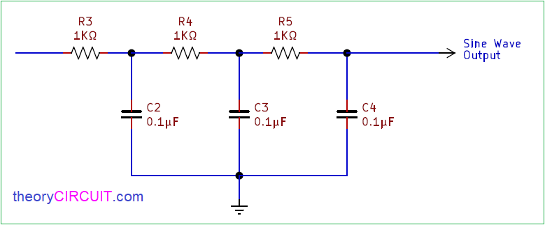
By connecting this Resistor capacitor network at the output we can get sine wave output at the end. By changing the value of network resistor and capacitor we can get different amplitude sine wave but the frequency will depends on the IC 4047 output square pulse.
IC 4047 Pin details
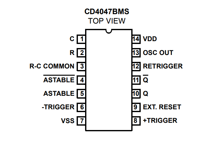
CD4047 is a dual inline package astable, mono stable multivibrator, it has 14 functional pins, it can take upto 15V as bias and gives peak to peak output pulse.