
Last Updated on March 16, 2024
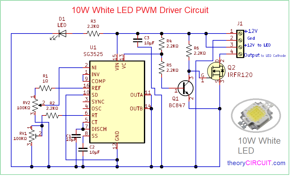
Simple and easy to Construct 10W White LED PWM Driver Circuit designed by using IC SG3525A. IC SG3525A from On Semiconductor is a pulse width modulator control circuit Offers improved performance and lower external parts count when used in designing all types of switching power supplies.
IC SG3525A operates with voltage Range from 8.0V to 35V. It can oscillate output frequency from 100Hz to 40KHz suitable for most LED Driver circuit design. It has latching PWM feature to prevent multiple pulses. This IC available in SMD and THT packages.
Circuit Diagram
Components Required (BOM)
| 1 | C1, C2, C3 | 10µF | C_0805_2012Metric | 3 | ||
| 2 | R2, R3, R4, R5, R6 | 2.2KΩ | R_0805_2012Metric | 5 | ||
| 3 | R1 | 1Ω | R_0805_2012Metric | 1 | ||
| 4 | D1 | LED | LED_0805_2012Metric | 1 | ||
| 5 | U1 | SG3525 | SOIC-16_3.9×9.9mm_P1.27mm | 1 | ||
| 6 | RV1, RV2 | 100KΩ | Potentiometer_Bourns_3296W_Vertical | 2 | ||
| 7 | Q1 | BC847 | SOT-23 | 1 | ||
| 8 | Q2 | IRFR120 | TO-252-2 | 1 | ||
| 9 | J1 | Screw_Terminal_01x04 | TerminalBlock_Altech_AK300-4_P5.00mm | 1 |
Construction & Working
IC SG3525 used as a 10W White LED PWM Driver. Here oscillator frequency range (fosc) decided by the value of oscillator timing Resistor RT and Oscillator timing Capacitor CT refer datasheet for more information.
In this LED driver circuit one 10 watt white LED connected at +12V to LED pin and output to LED cathode. MOSFET IRFR120 acts as a switching device and drives the LED according to the output from VC pin through Q1 transistor. In this circuit by varying the value of RV1 and RV2 we can adjust the dimming and brightness level of 10W LED.
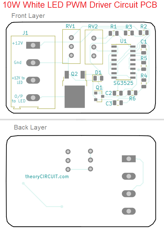
Printed Circuit Board
10W White LED PWM Driver Circuit Gerber files.
Interactive Board Viewer


I’m converting halogen microscope bulbs to leds. I’d like to try this circuit to use a 10 W led and have it dimmable by manipulating RV2. But in your circuit diagram you use a 10µF for C1 where the datasheet of the SG3525A specifies that capacitor from 1 to 100 nF.
What am I missing or is this an error?
Please keep it simple, I’m a chemist, not an engineer in electronics.
Thanks.
Hi Peter Cleemput.,
Yes you are Right, there is a annotation error. Use a capacitor in the range of 1 to 100 nF for C1 that is Oscillator Timing Capacitor range from 0.001 µF to 0.1 µF. Using a 10µF capacitor instead might affect the performance of the circuit. I would advise replacing C1 with a capacitor within the specified range mentioned in the datasheet (1 to 100 nF) to ensure proper functionality and compatibility with the SG3525A. If you have any further questions or need clarification, feel free to ask theroycircuit.
Can I integrate this driver to Arduino for providing pwm input