Last Updated on February 5, 2026
While working on signal testing and basic R&D setups, I often need a simple sine wave source, at low to mid frequency also in a handy portable package, so that i can avoid using bulky function generator every time. I decided to build a reliable RC Phase Shift Oscillator by using an Op-Amp IC 741.
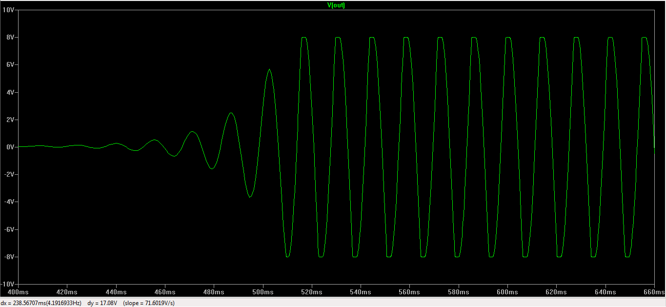
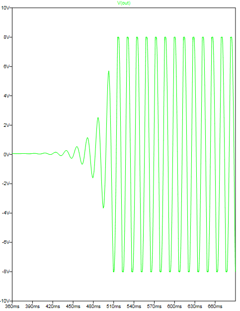
This circuit is easy to understand, uses very few easily available components but had a doubt about the oscillation and output signal amplitude so before going to prototype i used LT Spice to simulate the circuit.
Circuit Diagram
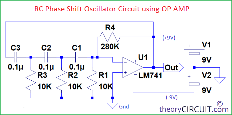
Components used in Simulation
- LM741 (Get LM741 Symbol and Library for LT Spice here)
- Resistor 10KΩ = 3
- Resistor 280KΩ = 1
- Capacitor 0.1μF = 3
- 9V battery = 2 to form dual power supply (+9V GND -9V)
RC Phase Shift Oscillator
We know that Resistor and Capacitor Oscillator with amplifying device forms RC phase shift Oscillator. It is capable of generate sine wave and amplifier attached with RC network provides gain to signal. Here we use IC 741 op-amp, this circuit does not need any external input signal, once power is applied it will automatically generates a continuous sinusoidal waveform.
Basic Working
We know that any oscillator that satisfy Barkhausen criteria that is total phase shift around the loop = 360° = 0° and loop gain ≥ 1 will oscillate signal continuously.
RC Network Phase Shift
Here I used 0.1μF capacitor and 10KΩ Resistor in RC Network. I used total three stage RC components, each RC section provides approximately 60° phase shift. Total RC Phase shift = 60°+60°+60° = 180°
Op-Amp Phase Shift
Here the IC 741 op-amp is used in a inverting configuration so it will produce 180° phase shift to the input signal.
Total phase shift = 180° (RC Network) + 180° (Op-Amp) = 360°.
We need dual power supply +9V, -9V so that circuit give symmetrical sine wave output and proper internal biasing of LM741 happens. We can calculate the output frequency as.,
f = 1/(2πRC√6)
By applying the components value we get f = 65 Hz, for the circuit i simulate. Here is the simulation and output signal. So now i peacefully go for prototyping.
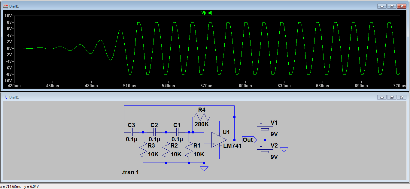
Output signal starting from Oscillation