Last Updated on March 16, 2024
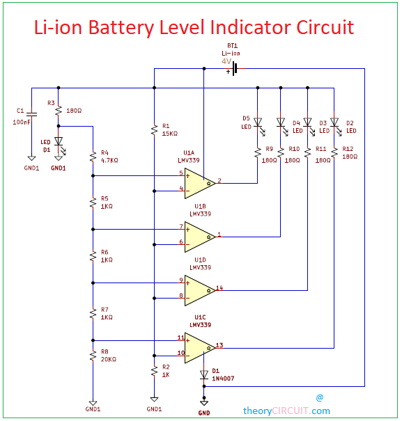
For sensing the terminal voltage levels of the battery series, LM339 IC is used. LM339 from Texas Instruments is a single supply quad comparator which has four channels to detect the magnitude of Analog voltages and indicate the voltage level by lighting up to 4 LEDs. So, the IC is designed to indicate four voltage levels respective to a common voltage reference. For voltage indication LEDs can be connected to the IC.
This circuit designed to measure up to 4V supply from li-ion battery, and most suitable for 3.7V 800mAH battery. Use Reverse voltage protection diode with lithium ion battery if you are implementing this circuit in sensitive applications.
Circuit Diagram
BOM
| S no | Designator | Value | Quantity |
| 1 | IC | LM339 | 1 |
| 2 | C1 | 100nF | 1 |
| 3 | R1 | 15KΩ | 1 |
| R2 | 11KΩ | 1 | |
| R3 | 180Ω | 1 | |
| R4 | 4.7KΩ | 1 | |
| R5,R6,R7, | 1KΩ | 3 | |
| R8 | 20KΩ | 1 | |
| R9,R10,R11,R12 | 180Ω | 4 | |
| 5 | LED | 5 | |
| 6 | D1 | 1N4007 | 1 |
Construction and working
The Functioning of this circuit is based on the comparator. A comparator compare two input signal and gives the output indicating which one is larger. If inverting pin of LM339 IC is higher than non-inverting than output is low otherwise it is high. This concept of comparator can be used in sensing the desired voltage level. When Li-ion battery is connected to the R3 resistor and LM339 IC.
The voltage at inverting pin (4th,6th,8th and 10th pin) of all the comparators are same and will vary as per the change in battery voltage. The resistor R1 and R2 makes a resistor divider network which always provides 1/3rd of the battery voltage to the inverting pin of the comparator. When inverting input of the comparator is at high voltage than the non-inverting pin then the output voltage of comparator is low otherwise it is high. This make cathode of the output LED at low voltage and the anode of LED is already at positive of the battery. This will turn on the LED which will indicate the voltage level of the battery in other case, the LED will be in off state. Use the LED colors as you want to indicate in the particular level.


Hi,
Which LED indicates the full charge level?
Hi Marujju
In Li-ion Battery Level Indicator Circuit, there is a error in schematic diagram that is LED D1 replace it with 6.2V Zener diode.
and then LED D5 will indicate the full charge level.
Hello,
I was wondering how you decided on what values to use for the five resistors, namely from R4 to R8. I know that they should be calculated with the lithium battery discharge in mind and for my project I will need to use 6V, but I am not sure what resistor I should use.
Hello Dimi
To adapt the circuit for a 6V battery, calculate the voltage divider resistors (R4 to R8) based on the desired reference voltages. Use the voltage divider formula to find the appropriate resistor values, ensuring that the comparators will switch states at the correct battery voltages.
Hello, which specific software did you use to run the simulation of this circuit ? And do I have to vary the voltage of the battery to see which LEDs turn ON?