
Last Updated on March 16, 2024
Three Siren Sound Generator Circuit Using UM3561 can be utilized in several applications, we know different siren sounds are used for many field based applications, here the following circuit can produce three different siren sounds (Police siren, Fire engine siren, Ambulance siren).
By using single IC UM3561 we can build three siren sound generator circuit. It will help your sound based or alarm based electronic project. the UM3561 is low cost, low power CMOS LSI IC. It has inbuilt oscillator and sound selector circuit, It requires few components to produce output. It can easily drive magnetic speaker with a help of single NPN transistor.
Three Siren Sound Generator Circuit diagram

Components Required
- IC UM3561
- Variable Resistor 100KΩ
- Resistor 560Ω, 100KΩ, 10KΩ each one.
- Transistor NPN BC547
- Speaker 8Ω
- Zener diode (3.3V)
- Push button switch 3
- Battery 9V
- Bread board
- Connecting wires
Construction & Working
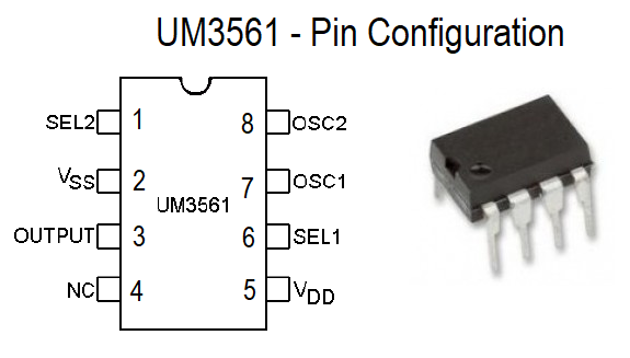
The UM3561 has 8 pins, and it can intake 3 to 5V as a power supply and gives output range -3.0V to +3.0V, 9V battery gives bias to the whole circuit, to regulate the battery voltage Zener diode (3.3V) is used across bias lines. Select line 1,2 are connected with three push to ON switch and oscillator pin 7, 8 are connected with variable Resistor VR1 and R1 to maintain oscillation.
Output pin is connected to the 8Ω speaker through NPN transistor, when the switch S1 pressed Ambulance siren will generate, when the switch S2 pressed fire bridge siren will generate, when the switch S3 pressed machine gun siren will generate at output. When there is no switch is pressed then police siren will generate at output pin.
Pin Configuration
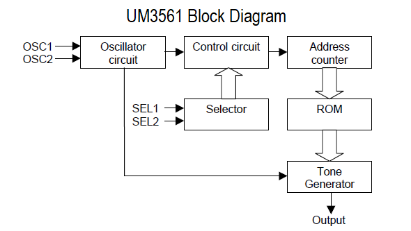
Block Diagram
Sound Effect selection
Different siren sound can be selected by biasing SEL1 and SEL2 pins.
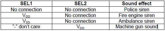
The UM3561 has sound effect ROM and it is organised as 256 words by 8 bits. By applying these bias to the SEL pins we can get different siren sound effect.
The Zener diode in the circuit diagram is not connected the correct way. You ae supposed to connect Vdd, the speaker positive terminal and the left side of the switches to the zener cathode to give the circuit the regulated 3 V. With the connection in the above diagram the components get 9V and will just fry.
nice work sir, but sir where can i see the ic um 3561 to buy?
Managing Director,
Theory Circuits
Dear Sir,
I wish to use this IC to produce Machine Gun sound to drive away monkeys
without disturbing the neighborhood at a modulated frequency of 15Khz ~ 25 Khz.
Could you please let me know the value of the oscillator resistance to
achieve this frequency.
Awaiting a favourable reply,
Best Regards,
Ronald Fonseka,
SRI LANKA