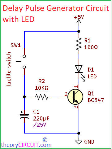
Delay Pulse Generator Circuit have a lot of hidden applications, that can be used in any…
Continue ReadingCategory: Analog
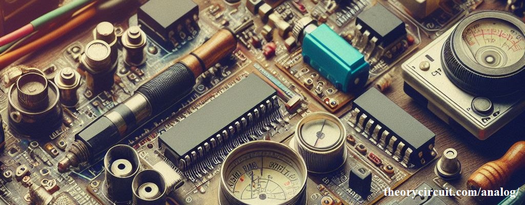
theoryCIRCUIT brings you Analog Electronics Circuits and Projects, where signals are continuous and components operate on varying voltage levels. Explore circuits, theories, and applications rooted in the fundamentals of analog technology. Get involve in the design, analysis, and implementation of circuits that manipulate analog signals, such as voltages and currents and more.
Voltage Booster Circuit using Transistor
A Circuit used to increase the voltage output is known as voltage booster circuit, it can…
Continue Reading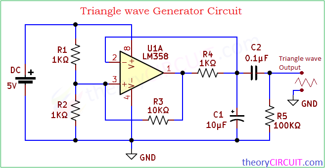
Triangle wave Generator Circuit
A non-Sinusoidal waveform with linear rise and fall in the shape of Triangle from zero axis…
Continue Reading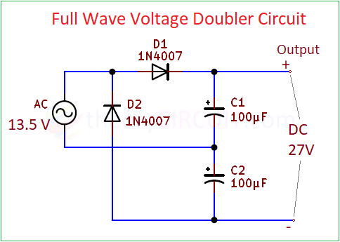
Voltage Doubler Circuit
Voltage Doubler Circuit or Voltage Multiplier circuits are used to get higher DC Voltage than the…
Continue Reading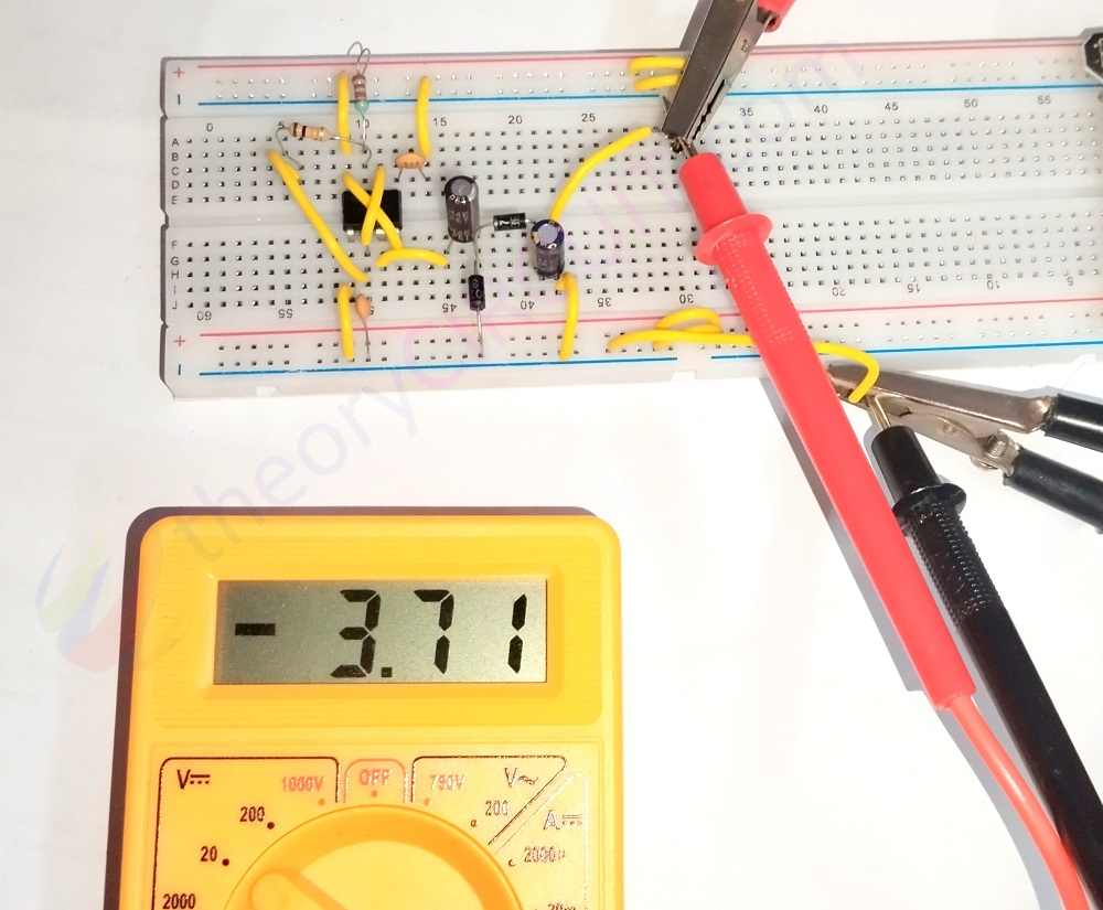
Negative Voltage Generator Circuit using IC 555
As we know Operational Amplifiers, Sensors and some Signal Conditioning circuits requires Negative Voltage as bias…
Continue Reading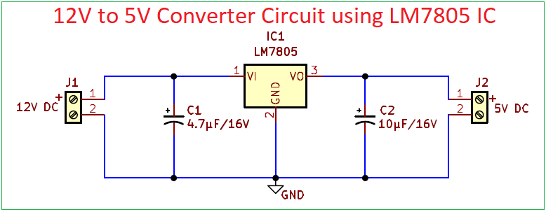
12V to 5V Converter Circuit using LM7805 IC
Most Electronic Components and Microcontrollers requires 5V DC power supply to operate smoothly, Arduino and Raspberry…
Continue Reading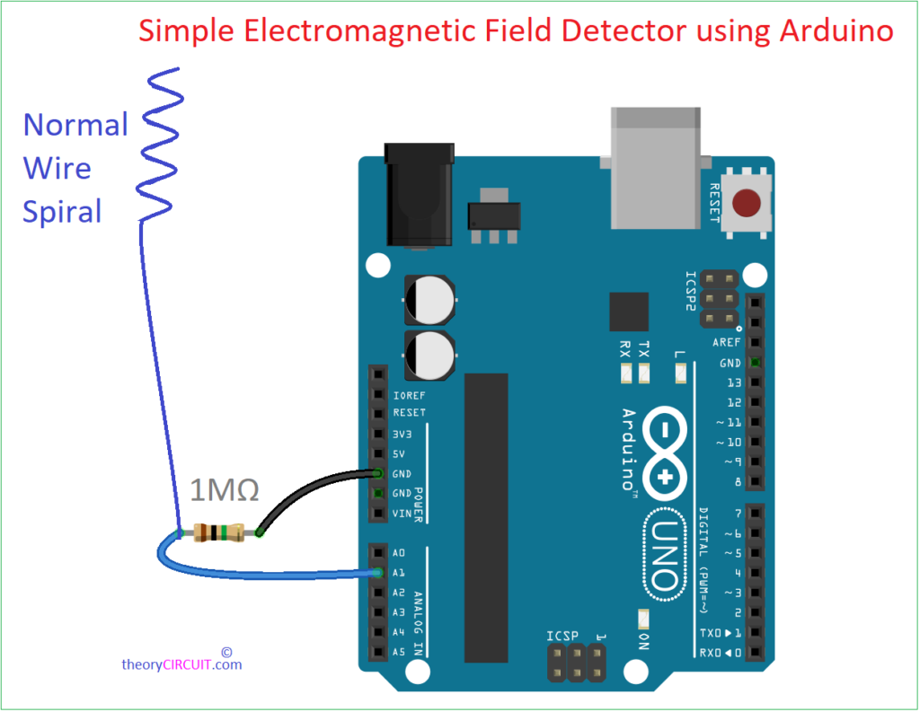
Simple Electromagnetic Field Detector using Arduino
An electromagnetic field Shortly EMF is a physical field produced by electrically charged objects and flow…
Continue Reading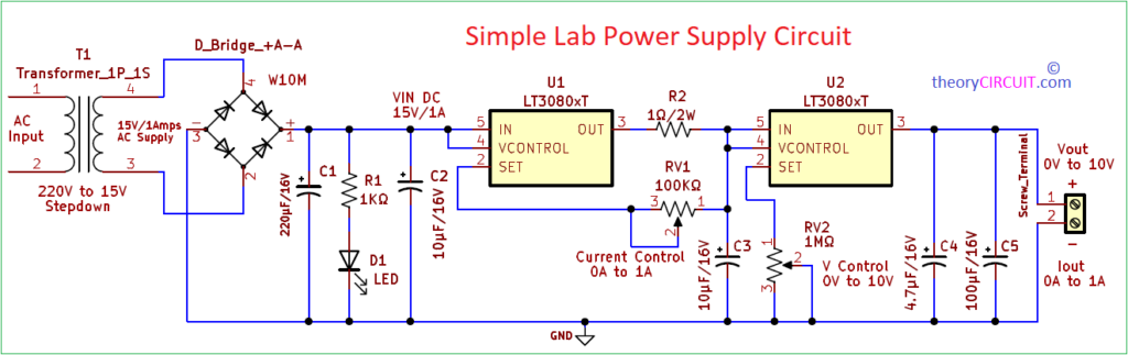
Simple Lab Power Supply Circuit
If you are an Electronic Engineer, Student or Hobyist then i don’t need to tell you…
Continue Reading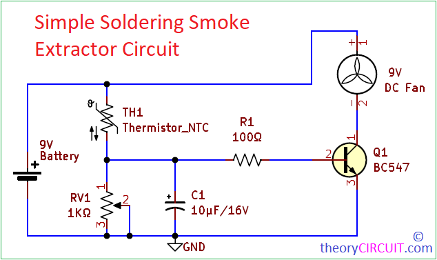
Simple Soldering Smoke Extractor Circuit
As electronics enthusiasts and professionals, we often find ourselves immersed in the soldering process, creating intricate…
Continue Reading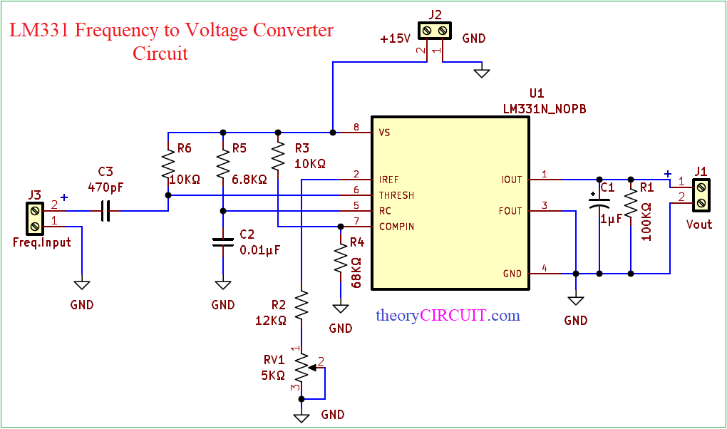
Frequency To Voltage Converter Circuit using LM331 IC
Frequency to Voltage Converter Circuits are very useful in applications like Speed & RPM Measurement, Flow…
Continue Reading