
Last Updated on March 16, 2024
Amplitude Modulation Radio or AM Radio is a broadcasting technology that modulates the amplitude of Carrier Signal to carry information. AM radio waves typically cover the frequency range of 530 kHz to 1700 kHz in the medium frequency (MF) band. Carrier signal of Commercial AM Radio Channel will lie between these range. Some Countries allows some portion of Radio Frequency spectrum for hobbyist and experimenters. If you Want to listen the AM Radio Channel you need one AM Radio Receiver. You can diy Simple AM Radio using Transistors and it is very easy to make, but the tuning is the hard part..!
Let us Understand what is AM Radio Wave and its shape before jump into the Receiver circuit, As previously said A Carrier signal between Medium Frequency range will be Oscillated by the Tank circuit placed in a AM transmitter and then Voice Input through any source Like Microphone, Audio Tape will be fed into Modulator circuit. Here the Amplitude of Carrier signal will changed in according to the Audio Signal. We know Frequency of Audio signal lies between 20Hz to 20KHz, hence it can easily sit on top of the carrier signal.
AM Radio broadcasting will follow some modulation technics and modulation index (m = 1 is known as 100% modulation), resulting AM wave, when plotted on a graph, often exhibits a symmetrical or mirror like shape. This symmetry arises from the modulation process where both positive and negative peaks of the audio signal cause corresponding changes in the amplitude of the carrier wave.
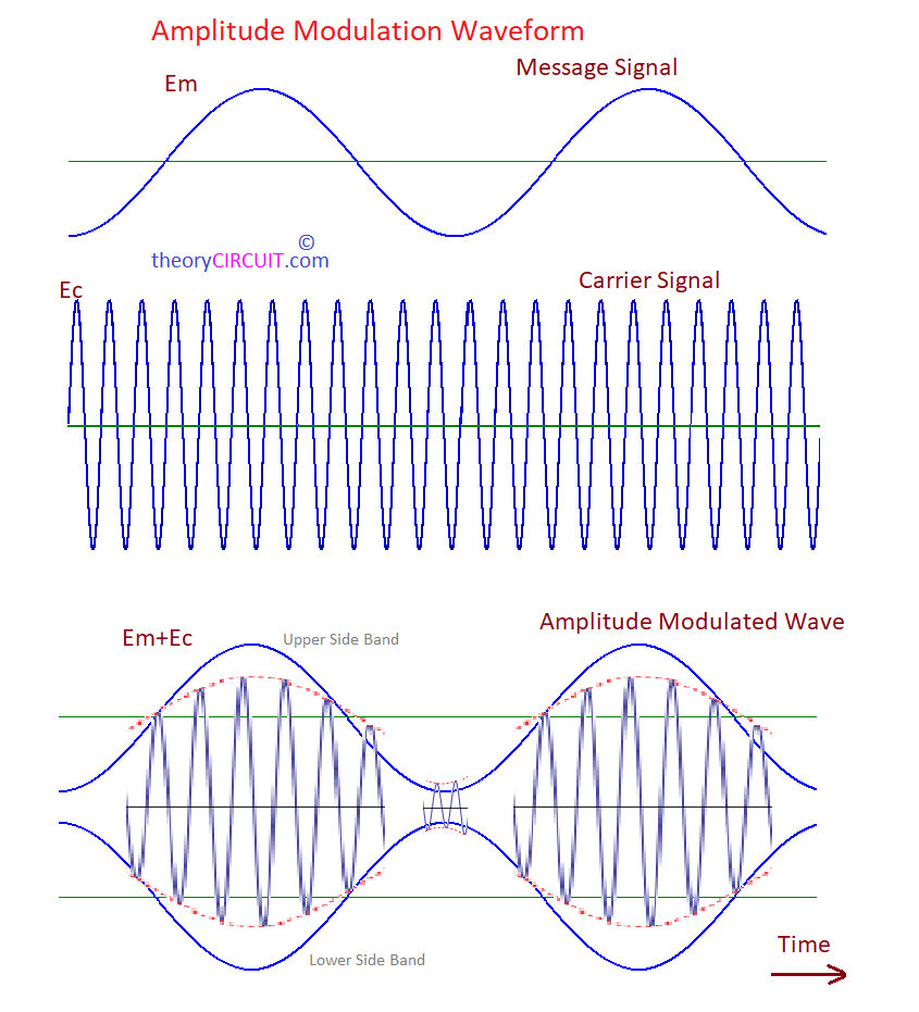
In AM Receiver we will clip and remove lower side band and use Upper band to demodulate the Audio Signal.
Circuit Diagram
Components List
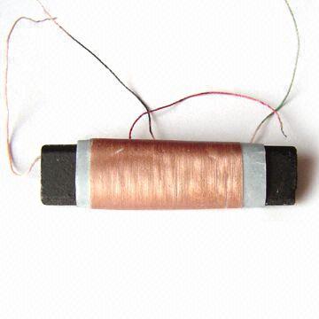
- AM Radio Ferrite
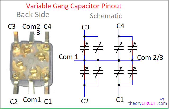
- Variable Gang Capacitor
- Capacitor 10pF, 1nF, 100nF each one
- Electrolytic Capacitor 10μF/16V = 2, 220μF/16V = 1
- Germanium Diode OA91
- Resistor 100KΩ, 430KΩ, 12KΩ, 2.2KΩ each one
- Variable Resistor 10KΩ
- Transistor 2N4403 NPN, 2N4403 PNP each one
- Audio Amplifier IC LM386
- 8Ω Loud Speaker
- 9V Battery
Construction & Working
Construction of AM Radio Receiver Circuit starts with local tuning Setup, AM Radio Ferrite coil and Variable Gang Capacitor makes the Local Oscillator and Resonates with the tuned channel and Removes the Carrier Signal and then Germanium diode (0.3V cut in voltage) will allow the positeve side that is upper side band and removes (Rectification) the lower side band. Now we have Audio signal of tuned AM Radio Channel, due to the low frequency characteristics of AM Wave there will be lot of noise added with original message signal to remove those noise, capacitor C3 (1nF) is used. after the filtering, Two transistor pair (2N4401 and 2N4403) pre amplifies the audio signal.
Transistor 2N4401 Pinout
Transistor 2N4403 Pinout
Pre-amplified Audio Signal is fed into Audio Amplifier circuit designed by using LM386 through Variable Resistor RV1, this will act as Volume Control. At the output of Audio amplifier 8Ω loud speaker is connected to reproduce audio signal into sound. This circuit can be operated with 9V battery power or with 9V DC adapter power supply.
Important Points to Note:
- Choose AM Radio Ferrite Coil Depends on the Frequency Range you want to Receive.
- Choose Variable Capacitor depends on the Frequency Range you want to Receive.
- You can use CAP TRIMMER 150-500PF instead of Gang Capacitor.
- You can use discrete 240μH Inductor and 365pF Variable Capacitor for tuning circuit. Make sure that you are receiving right signal.
- Proper Antenna is necessary to receive the AM Radio Wave. There is lot of antenna for am radio receiver available in the market.
- If you are using AM Radio Ferrite Coil then you can use simple Wire or dipole Antenna.