Last Updated on March 16, 2024
Li-ion Batteries are commonly used in various electronic devices and it require a controlled charging process to ensure optimal performance, longevity and safety. Unlike some other battery types, Li-ion batteries are sensitive to overcharging, which can lead to overheating, reduced capacity, and even safety hazards such as swelling or leakage. So we need a dedicated battery charging circuit to manage the charging process efficiently. In some applications we deploy battery as a additional power source intended to use during power failure or interruption. In such case we have to switch bias of system between two sources. Here is the simple Dual Input Li ion Battery Charger Circuit suitable for such case and it can effectively work with 5V Single Cell Li-ion battery.
About IC MAX1555
MAX1555 and MAX1551 from maxim integrated is a SOT23 Package Dual input USB/AC Adapter single cell Li Ion Battery charger integrated circuit. This IC operate with no external FETs or diodes, and accept operating input voltages up to 7V. It is a linear charger, meaning it regulates the charging current by adjusting the voltage drop across a series pass transistor. The MAX1555 is designed to work with a variety of power sources, such as USB ports or AC adapters, making it versatile for different applications.
It contains Thermal Regulation circuitry to prevent the battery from overheating. The MAX1555 includes a CHG’ output to indicate charging status, it goes low when the charging threshold matches. As per the Datasheet claim “With USB connected, but without DC power, charge current is set to 100mA (max). This allows charging from both powered and unpowered USB hubs with no port communication required. When DC power is connected, charging current is set at 280mA (typ). No input-blocking diodes are required to prevent battery drain. Datasheet
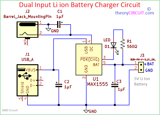
Circuit Diagram
Components Required
| 1 | C1, C2, C3 | 1μF | CP_Elec_5x3 | 3 | ||
| 2 | R1 | 560Ω | R_1206_3216Metric | 1 | ||
| 3 | D1 | LED | LED_1206_3216Metric | 1 | ||
| 4 | U1 | MAX1555 | SOT-23-5 | 1 | ||
| 5 | J1 | USB_A | USB_A_CONNFLY_DS1095-WNR0 | 1 | ||
| 6 | J2 | Barrel_Jack_MountingPin | BarrelJack_Kycon_KLDX-0202-xC_Horizontal | 1 | ||
| 7 | J3 | B2B-PH-K-S_LF__SN_ | JST_EH_B2B-EH-A_1x02_P2.50mm_Vertical | 1 |
Construction & Working
This 5V Li Ion Battery charger circuit designed with dual input power source way, one is from Adapter and another one is from USB. Both are connected to thier respective terminals in MAX1555, here 1μF SMD capacitors are used as bias filters. A LED is connected to the CHG’ terminal to indicated the charging status.
The MAX1555 can charge from either the USB input or the DC input. The battery does not charge from both sources at the same time. MAX1555 automatically detect the active input and charge from that. If both power sources are active, the DC input takes precedence. The switchover between DC and USB depends on the following conditions, If VDC > 3.95V AND VUSB DON’T CARE = 280mA typical charging from DC Source. If VDC < 3.52V AND 3.95V < VUSB < 6V = 100mA (max) charging from USB Source.
With USB connected, but without DC power, the charge current is set to 100mA (max). This allows charging from both powered and unpowered USB hubs with no port communication required. When DC power is connected, charging current is set at 280mA (typ). The MAX1555 do not feature an enable input. Once power is connected to USB and/or DC, the charger is on. When input power is removed, battery leakage current is less than 5µA. No input-blocking diodes are required to prevent battery drain. Insert a diode at DC (the adapter input) if protection from negative voltage inputs (reversed-polarity adapter plugs) is required.
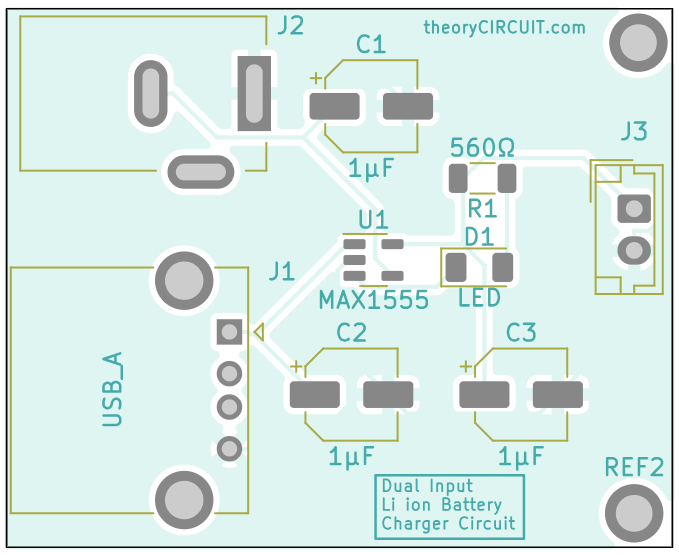
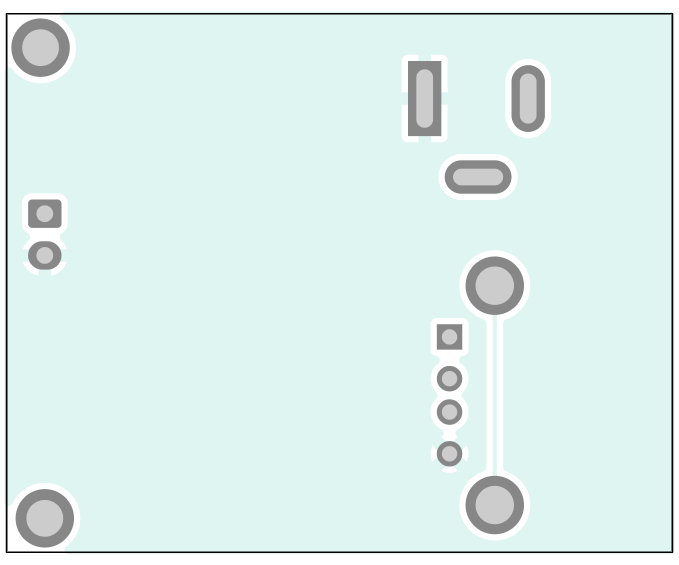
Printed Circuit Board
Dual Input Li ion Battery Charger Circuit PCB Front Layer
Dual Input Li ion Battery Charger Circuit PCB Back Layer
Dual Input Li ion Battery Charger Circuit PCB Gerber File.
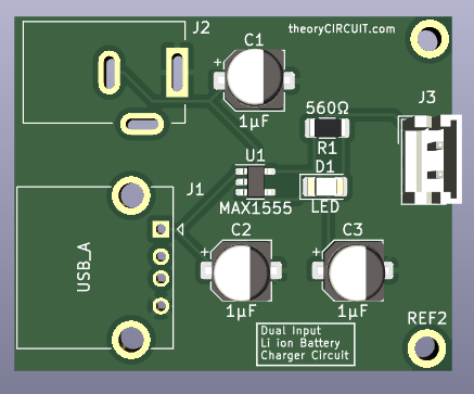
Interactive Board Viewer
PCB 3D View


What is the purpose of having dual input sources in a Li-ion battery charger circuit, and how does it contribute to the functionality or versatility of the charger design?
Hi Qwer
The dual input sources in a Li-ion battery charger circuit provide flexibility for charging from different power sources. It allows the charger to be powered either from a traditional AC adapter or through a USB port, enhancing convenience and compatibility with various devices and power supplies.
Hello good time.
This circuit is designed to charge a battery with a capacity of one cell
But I want to charge two batteries in parallel using this charger.
Therefore, I have to use a 2N2222 transistor to increase the current at the output of the circuit.
Please help me to design the schematic and PCB.